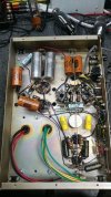
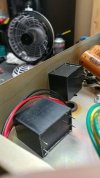
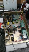
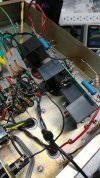
active circuit measurements, most recent as of todays timestamp:
mains 120v, idle 43w (plus 0.2w or whatever from the power strip being used)
b+ = 215v
b1 = 203v
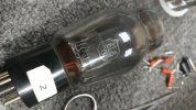
6L6g cat = ~18v
all voltages with reference to circuit ground
*didnt think to measure grid-1 voltage with ref to gnd. need to start measuring from cat-to-g1 in future for -v bias number.
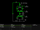
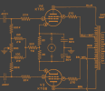
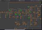
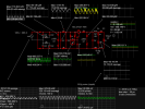
better picture of the electrical situation. output tube resistance equivalent based off of real circuit measurements, voltages across resistors +/- real world tolerance variances. voltage drops are a close approximations derived from ideal circuit sim parameters. a resistor doesnt measure perfect out in the real world, no do tubes.
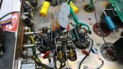
measurements of each side of the bias ladder (pot tuned for balanced dcv between factory test points)
[cathode / cathode]
17.8v / 17.9v
[68r / 68r]
16.2v / 16.2v
[220r 2w flameproof]
5.29v / 5.29v
[68r / 68r]
3.33v / 3.88v
[pot: 150/150 if centered]
*still need to verify actual pot resistances (full vs wiper positions)*
clearly one output bottle needs a little more electron love than the other. if only i had focused on who had the higher number. hmm, things may have been handwritten from left to right although measured inside tube to outside tube (hypothesis pending).
**previous snapshot showed 151r for out-txf voltage drop. it has been corrected with measured dcr.
still need to post a clean & updated version of working schematic in the falstad sim. the sim has its limitations and faults but its better than guessing.