• The move to the new server is done. There are some software and database maintenance updates in process. This has us passing the hat around to help out. We appreciate any donations. Seriously, even a dollar helps. The payment page may be found here - https://www.audiokarma.org/support.html
i wonder if bumping up the g2 resistor is a quick and easy way to limit the max usable output of a tube amp. to protect the out-txf from an over-powered design.

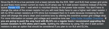
Screenshot 2026-06-29 at 13-44-30 Amp Mods.png

*text search (ctrl+f) for fender 470 for quick location of the paragraph, its a long page of text.
 
more bias sim updates, its ever evolving until project complete i.e. job done (sounds better with british or scottish accent).

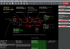
Screenshot 2026-06-29 at 13-58-44 6L6g bias sim v3.txt - Circuit Simulator.png
modeling the currently installed 4.7k g2 setting and the 255r ladder core. the 6L6g numbers still need to be dialed-in due to the 360v b+ setting. havent found a quick and easy load line sim that doesnt ask too many questions. also good to know that the 16309 out-txf was measured by dcg-designs at 8600r. rather amusing to see sales sites quote 10k.

sim data file attached.
 

Attachments

i wonder how many va the mains-txf is rated for?

looking at the schematic and the following numbers:
455+455 x 0.14 = 127.4
+
6.3 x 4 = 25.2
+
5 x 3 = 15

total of 167.6

either 180va/200va/220va depending on if there is any safety padding i.e. 80% utilization.
 
i wonder if bumping up the g2 resistor is a quick and easy way to limit the max usable output of a tube amp. to protect the out-txf from an over-powered design.
yes but its a bad one. You'd be better off reducing the screen voltage but keeping it a stable supply rather than letting it shift around so much. That will allow for more consistent performance across the usable power range. With a mushy supply the distortion performance tends to get a fair bit worse as power output increases. Lower screen voltage reduces how much current the tube can swing so less power output. Makes for a happier match into a fairly high Z transformer too.
 
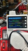
anyone know what the stock amp should idle at in terms of mains wattage?


heathkit w5m - 27.jpg
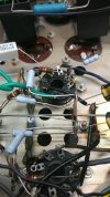
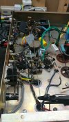
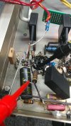
closer look at bias ladder area and resistors. rg1 was updated to 10k vs 22k factory shown above. rg2 shown as 220r, currently 4.7k for testing and soon to be revised again.

heathkit w5m - 28.jpg
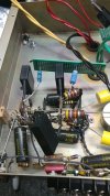
looking at the front end, some updates are needed, lower right corner 0.1uf cap (original) updated plus the 47r next to it which measured 62r (slightly out of tolerance).
 
heathkit w5m - 29.jpg
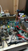
installed a cap modified switch for delayed startup after plugging in power. looks like around 8 seconds for the heaters to wake the vacuum connections into becoming a load. have to try and model that in the circuit sim.

big issue with using an inverted v-doubler is that a low load pumps up the idle voltage by way too much too soon. drawback to a load sensitive design. have to design a 555 relay timer circuit for safety instead of using a 50w bleeder system to take the hit.

ideally some type of easy self-tuning throttle would be nice although a simple smps would be better.

heathkit w5m - 30.jpg
10k rg1 and 4.7k rg2 were tested. shifting away from the out-txf screen taps as others have suggested for the latest circuit version (not shown). went down to 470r rg2 and two 140v zeners plus a dropping resistor (62k too much, 47k possibly ideal based on testing and measurements).
 
heathkit w5m - 31.jpg
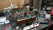
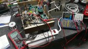
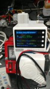
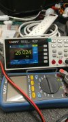
taking some measurements, two of the three meters connected. ladder bias core and front end ht. also using a cute little sae preamp to boost the input signal, passive preamp can only get you so far.

heathkit w5m - 32.jpg
idle number are higher with the circuit version shown above. also 4r output parallel speakers have more punch.
 
heathkit w5m - 33.jpg
more adjustment, ladder core and b+. once again light color owon just sitting and measuring the air.

heathkit w5m - 34.jpg
idle responding to adjustments, in this case changing front end caps to higher parallel value.

these trial and error adjustments are rather tedious and not worth documenting, boring content. will post revised sim schematic and more up to date photo notes. have adjusted the current version being tested over to bce design mode (bean counter edition) to compare noise output vs filter darlington design. so far ears indicate bce circuit should be adequate for normal listening environments. at least the npn design reached proof of concept testing before being shelved.

also updated the current front end circuit (heathkit) to remove out of spec carbon comp schtuff, 47k measuring 25k is not a good thing to see. i should also modify the factory schematic to better show what has been changed, instead of all this typing...
 
also comparing output tube choices and what would be a good recommendation for the current owner for future investment. physically small glassware is not an issue, owner isnt interested in flashy over-sized (possibly gold font) bs which is far too prevalent.


sticking with something that has a 0.9a heater rating would be nice, less mains-txf stress which can yield higher system longevity. doing more with less can be quite enjoyable but its not for everyone.

7027a still on the list of contenders.
 
suppose i should post the primary sim link every so often so that new viewers are not immediately lost as to what sim software is being used and no installation is needed, just an internet connection and browser. although an offline version of falstad sim exists somewhere on his site.


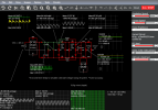
Screenshot 2026-06-29 at 20-26-53 6L6g - y26m06d29 bean counter.txt - Circuit Simulator.png
reduced parts, going the non-darlington filter route for comparison and removed parallel r+c on front end. above shows circuit with 130v mains

went the "reduced component count" route even though thats not entirely accurate when factoring in heater offset add-on and grid-2 regulated supply (somewhat). plus an upcoming 555 circuit for relay control, possible runaway detection/reaction too.


Screenshot 2026-06-29 at 20-27-46 6L6g - y26m06d29 bean counter.txt - Circuit Simulator.png
for comparison, 120v mains activity via the sliders available on the sim

sim data file attached.

330k in parallel with a timed relay is for sim testing. does not and will not exist in physical reality builds.
i have yet to find a programmable load (resistance) for the sim, cant say i have put much effort into finding one either.

to be able to program in a custom load curve based on bench circuit measurements would be nice.
 

Attachments

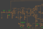
i suppose its pirate treasure map time, lots of xx's on this one.
6L6g sch 01jul page-1.png
changed some values as noted although original carbon comp still exist and need to be purged from the circuit.

6L6g sch 01jul page-2.png
eventually this amp might go fixed bias like the dcg-designs example but for now its easier to keep the bias ladder. until it becomes too much of an issue (film bypass caps, physically large).
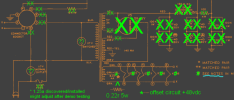
6L6g sch 01jul page-3.png
lots of treasure on this map, mr krabs would be pleased (season 1 ep 17a).

mains cord was rewired for direct connection, connector socket deleted for the most part. tube numbers are 12au7, 5814 and 6L6g if the previous photos were insufficient (no photo of 12au7 in front position).

more values might get updated as time goes on. have to build the final layout in the chassis with high wattage values and then final mile fine tuning which includes thermal imaging. with the ht secondary no idea which side is being used with center tap, just a guess on the schematic.

custom b+ board obviously connecting to one of the 455v txf half tap's. eventually need to balance power consumption on the front end. looks like dcg-designs focused on 3.5ma per triode (7ma per bottle).

heater offset circuit will either have 47v 5w or 51v 5w single zener diode. g2/screen will have 130+130v 5w zener's plus a suitable dropper around 56k feeding them.

custom 5v step-up to 12-15v pcb txf will be on the shopping list even though a v-tripler circuit is possible. it will feed the timer relay for precise startup every time. could also feed overload (no tubes installed) type of protection circuit.

 
revising the non-npn circuit a little more and the potential of eliminating the inverted v-doubler front end is looking favorable. initial testing still needed but changing over to a film cap feeding a bridge rectifier module (one component vs 2-4 diodes) seems like a better plan. cooking some simulations and the numbers look good. the inline single cap will function as a step-down load sensitive solution. bce^2, bean counter squared?

maybe try installing a 200ma fast blow for extra protection if a tube has a meltdown or lower resistance due to age. if the b+ circuit gets hit with a dead short the front end capacitor will act like a dim-bulb and the circuit will brown-out and crash. how that will affect the inline cap in terms of continued current flow is pending some sim activity.

going to the inline cap also reduces the voltage across it vs the v-doubler needing 1kv dc / 650v ac or higher. more sim testing needed.

next batch of parts shopping in progress with high wattage chassis mount components to help lock into a final form factor / footprint. found my past sim data with 555 timer circuit so that can move forward as well.

the project continues forward, ever so slowly. learning curve on the 1st of something is always taller than mount everest [Sagarmāthā in Nepal / Qomolangma in Tibet Autonomous Region].
 
on another design note, extreme thermal management modz territory (no liquid hydrogen to purchase).

heathkit w5m - 35.jpg
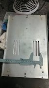
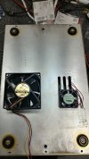
looking at the bottom panel vents and how a pair of 30x30mm low profile dc fans might help (each vent). running 24v dc fans at 12v would be comfortably silent at all times plus a significant amount of cfm to increase component service life.

heathkit w5m - 36.jpg
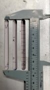
physical measurements for future reference, if the project goes in that direction after successful demo testing/critique is completed.
 
heathkit w5m - 37.jpg
front end needs more updating. color code looks like 4.7k and schematic says 47k

heathkit w5m - 38.jpg
and yet it measures 25k. component is also a hot spot around 180f or higher with the restrained b+ vs factory design norm.
 
any reason for making the decoupling caps between stages 20x smaller than the original design? That seems less than optimal for low frequency stability reasons.
 
excellent question and observation.

another experiment to evaluate circuit response. went with 1uf instead of 20 since its also easier to source 1uf film caps at the needed voltage, not quite dime-a-dozen but still cost effective. basic sonic testing so far shows no lack of bass with the 1+1 parallel bench speakers. even going from 100uf to 47uf for the cathode caps didnt impact bass response in a bad way.

trying to do a full-film renovation/redesign for improved longevity.
 
heathkit w5m - 39.jpg
fun task of figuring out how the three little pigs 30uf 600v film caps are going to be mounted

heathkit w5m - 40.jpg
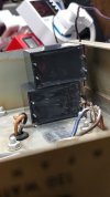
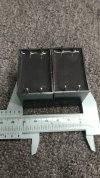
2 caps on their side is the same thickness as the chassis depth
 
heathkit w5m - 41.jpg
if the new caps are stacked for final installation there is one possible limiting issue. the mounting hardware for the chassis foot in this corner.

heathkit w5m - 42.jpg
comparing possible cooling fan sizes, if the project goes in that direction. 80x80 vs 40x40 from the scrap bin.
 
I made PCBs for mounting DC link film capacitors to a Keystone bracket so they can be properly bolted to a chassis. They were sized for KEMET's caps so not sure they'd fit yours but lmk the dimensions and I can check if you'd be interested.
 
I made PCBs for mounting DC link film capacitors to a Keystone bracket
good to know, these are definitely large film caps and also have larger than usual lead diameter so my usual hobby green board kit wont work so well. good thing point-to-point wiring is common for older tube amps.

ended up using hot melt glue and a solder tie point to the chassis. future photos will explain things better.
 
Back
Top Bottom