

You are using an out of date browser. It may not display this or other websites correctly.
You should upgrade or use an alternative browser.
You should upgrade or use an alternative browser.
heathkit w-5m renovations [boondoggle edition] quantum vacuum deep dive
- Thread starter sae-7125
- Start date

JonL
Lunatic Member
While I admire your tenacity in developing the circuit in your own way (and I won't pretend to understand everything you are doing), I have to say that Dave Gillespie's modifications of these amps works brilliantly and I think you'd be hard pressed to equal or exceed the performance of his design.

From Post #1:
I think your wall of words is much less informative than Dave's. And more drawn out. Sorry.highly informative although a wall of words which tends to be a migraine for some of us.

sae-7125
Super Member
a very valid point. except, going in a slightly different direction means the road less traveled even in 4x4 low.I think you'd be hard pressed to equal or exceed the performance of his design.
there were some design numbers that stood out as a red flag with dcg-designs. so i am exploring the heathkit design with a relatively minimal grasp of vacuum tube audio design theory (should be obvious by now) which oddly enough is similar to 1940s/1950s technology vs modern times/designs.
sae-7125
Super Member
going after 0.01% distortion or lower for a tube amp seems unnecessary, most people cant detect 20hz nor 20k not to mention how sensitive someone is at 0.1% distortion.
useful info and design data in dave's long worded analysis which helps set the stage for a few "what if" testing scenarios.
to be fair, my attempt at a design mod involves creating more sub-circuits vs original just like dave's. which is something that would have been nice to avoid since custom complexity can be a royal pain vs a simple and cheap recap.
redesigning within the confines/restrictions of certain existing components, namely the mains txf, is also proving to be a challenge.
designing an igbt based buck regulator / chopper circuit would be useful but the complexity is far beyond what should be considered.
at the end of the day, most of the things i am doing probably shouldnt be done but it is of r&d muse value to figure out why.
useful info and design data in dave's long worded analysis which helps set the stage for a few "what if" testing scenarios.
to be fair, my attempt at a design mod involves creating more sub-circuits vs original just like dave's. which is something that would have been nice to avoid since custom complexity can be a royal pain vs a simple and cheap recap.
redesigning within the confines/restrictions of certain existing components, namely the mains txf, is also proving to be a challenge.
designing an igbt based buck regulator / chopper circuit would be useful but the complexity is far beyond what should be considered.
at the end of the day, most of the things i am doing probably shouldnt be done but it is of r&d muse value to figure out why.
sae-7125
Super Member
the next batch of final design parts for the front end b+ circuit have arrived and now the headache of somewhat optimal circuit board layout plus placement within the chassis, without drilling holes or damaging the time-capsule. relay timer circuit layout aint gonna be pretty.
may end up deleting the cathode bypass caps completely, still too early for that decision.
 www.ampbooks.com
may end up deleting the cathode bypass caps completely, still too early for that decision.
Cathode Bypass Capacitor Calculator
Cathode Bypass Capacitor Calculator
Estimate cathode bypass capacitors for stages. Compare cutoff, reactance, gain lift, and standard values. Export clean results for careful workshop notes after calculation.
codingace.net
sae-7125
Super Member
also accurate and valid, hence the "boondoggle" designation so that people dont think this is an aerospace grade project nor anything to do with skunk works.I think your wall of words is much less informative than Dave's. And more drawn out. Sorry.
drawn out, i can agree with that as well. not exactly sitting at the bench 24/7 which tends to sabotage meaningful progress. nothing to be sorry about, it is what it is either way. useful thoughts/ideas/observations always welcome since this is an open project.
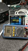
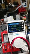
sae-7125
Super Member
i suppose, from a human psychology point of view, people are accustomed to quick multi-post cadence threads where 90% of the project is revealed before the end of page-1. and then the usual delicious measurement posts involving an oscilloscope, yeah i am an addict of those as well, show up before the end of page-2. a society addicted to instant gratification is not a healthy thing.
the hyper consumption of an over-stimulated digital populous has many trigger points, without getting into sympathetic vs para-sympathetic nervous system diagnostics and how emf/rf/other has a way of disrupting homeostasis (bruce lipton ions venue video). those of us with multiple head/cranial injuries on top of other health issues tend to have a lack of energy more often than not but also... a rather senseless addiction to killing time in front of internet. cervical spine lordosis of 42 degrees, who needs that and seems a bit excessive i.e. 20% or less should be fine... even though its not. digital neck syndrome anyone (text neck, tech neck)?
cant include "taking digital photos" as an addiction since most of my attempts are so sub-par its like the ball landed on the fairway of a golf course two counties over. definitely aint making birdie on that shot (who invented tree's anyway?).
and now, back to your regularly scheduled programming.
the hyper consumption of an over-stimulated digital populous has many trigger points, without getting into sympathetic vs para-sympathetic nervous system diagnostics and how emf/rf/other has a way of disrupting homeostasis (bruce lipton ions venue video). those of us with multiple head/cranial injuries on top of other health issues tend to have a lack of energy more often than not but also... a rather senseless addiction to killing time in front of internet. cervical spine lordosis of 42 degrees, who needs that and seems a bit excessive i.e. 20% or less should be fine... even though its not. digital neck syndrome anyone (text neck, tech neck)?
cant include "taking digital photos" as an addiction since most of my attempts are so sub-par its like the ball landed on the fairway of a golf course two counties over. definitely aint making birdie on that shot (who invented tree's anyway?).
and now, back to your regularly scheduled programming.
sae-7125
Super Member
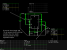
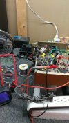
this will be a useful primer soon:
sae-7125
Super Member
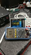
front-end 476v and b+ 431v
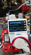
tested up to 128v even though 130-132v would be ideal. probably best not to run 6L6g or outputs with max design anode/plate voltage of 400v or less. the 7027a that are inbound should add some breathing room to address this limitation.
7027 | Vacuum Tubes | Amplified Parts
Browse products from the 7027 category - listing products sorted by popular, page 1
 www.amplifiedparts.com

maxhifi
Addicted Member
I rebuilt a pair last year. I etched the Sheldon Stokes power supply boards. I have a Variac exactly like yours dedicated to the W5Ms which feeds them 110V. More or less stock circuit except an added CL90 inrush limiter, and all passive components replaced with new. I could not replicate the turn off pulse David describes so didn't bother with the relay he suggests to add. I did not want to modify the output stage to fixed bias, because I like how cathode biased amplifiers sound, and don't need the extra power.
I think they're my best sounding amplifiers. Running original UK made KT66 power tubes. Hopefully, I get many reliable years out of them. Curious to see how your project turns out. My only complaint is you can't see the tubes better when they're in operation, and all the jacks are facing the wall.
I think they're my best sounding amplifiers. Running original UK made KT66 power tubes. Hopefully, I get many reliable years out of them. Curious to see how your project turns out. My only complaint is you can't see the tubes better when they're in operation, and all the jacks are facing the wall.
sae-7125
Super Member
excellent choice, using a variac for vintage tube gear should be standard practice vs 120v and hope the house doesnt catch fire.I have a Variac exactly like yours dedicated to the W5Ms which feeds them 110V.
good to know, i have not heard one of these in stock/factory condition or with a basic recap and resistor update.I could not replicate the turn off pulse David describes so didn't bother with the relay he suggests to add.
good choice. the extra power can damage the out-txf depending on part number. any issue with a -supply for fixed bias can cook outputs or at the very least shorten service life. i had some thoughts about a hybrid 100r cathode with -12v fixed but that hasnt gone anywhere yet.I did not want to modify the output stage to fixed bias, because I like how cathode biased amplifiers sound, and don't need the extra power.
maxhifi
Addicted Member
excellent choice, using a variac for vintage tube gear should be standard practice vs 120v and hope the house doesnt catch fire.
What pushed me over the edge, was seeing that I can't get the quiescent current of the KT66s down to the design level with 125V from my outlet. Given the cost of genuine KT66 tubes, and the track record of transformer failure with this amplifier, a cheap variac from Amazon looks like cheap insurance.
good to know, i have not heard one of these in stock/factory condition or with a basic recap and resistor update.
It is special. Maybe one of the best vintage amps I've ever heard.
good choice. the extra power can damage the out-txf depending on part number. any issue with a -supply for fixed bias can cook outputs or at the very least shorten service life. i had some thoughts about a hybrid 100r cathode with -12v fixed but that hasnt gone anywhere yet.
The bass-bal circuit which Heathkit devised already does a great job of compensating for a minor mismatch between output tubes. Changing it would effectively increase the already very high B+ voltage across the output tube plate to cathode.
I also am strongly in support of using KT66s, partially because it sounds different with 6L6GC, partially because I have KT66s, and partially because they're some of the best output tubes ever made.
In the 1970s a KT66 cost three times as much as an EL34, and was designed to last 8000 hours at maximum ratings!

what, specifically if you don't mind my asking? Thats not a prelude to any sort of argument, i'm just curious what you're seeing that I have spent zero time thinking about since I don't own a pair of these.there were some design numbers that stood out as a red flag with dcg-designs.
sae-7125
Super Member
cheap insurance is still infinitely better than no insurance. more than a few pieces of gear that go across the bench are proof positive of zero insurance preference out in the world. not everything ends up as a kaboom although the repair bill quoted might feel as though it did.the track record of transformer failure with this amplifier, a cheap variac from Amazon looks like cheap insurance.
unfortunately i have little experience with 6L6 vs kt66 sound quality either way. since the w-5m was designed for the kt66 then it should certainly sound best.I also am strongly in support of using KT66s, partially because it sounds different with 6L6GC
looking at anode-anode loading/impedance charts and various design numbers i wonder if doing an impedance mismatch when 6L6's are used would tip the scales. due to the very high b+ i wonder how far off the edge the lower rating 6L6/6L6g are being pushed.
it is interesting to see how using a ~600v b+ and a high value cathode resistor (or ladder of resistors) requires the use of cathode bypass caps which will have the greatest effect/impact vs lower b+ and lower cathode resistor value. perhaps i should consider adjusting a redesign strategy for 800v b+ and use 1k-1.5k cathode resistor... utilizing a voltage divider can be very wasteful especially heat generated across every resistor. not to mention out-txf dcr will heat up noticeably. should run some sim's and evaluate power consumption for various "hard to repair" components.
now we are talking some real fun + longevity.was designed to last 8000 hours at maximum ratings!
maxhifi
Addicted Member
I wouldn't raise the B+ under any circumstances. It would put more stress on the output transformer winding insulation, the tube sockets, and make an already dangerous amplifier even more dangerous.
As for tube ratings, the 6L6GC has the correct ratings. The 6L6, 6L6G, 6L6GB do not and should absolutely not be used here. They could short and blow a fuse or a transformer in W5M service. It's easy to get a decent set of 6L6GC at any guitar store, which would be robust enough to deal with the dissipation and voltages required in a W5M.
At this point the KT66 is specialized and rare. I have them because I like the Heathkit enough I want to squeeze the last drop of performance from it, and I value the history and look of the KT66 too. Just to make it work though a set of guitar store 6L6GC would be ideal
As for tube ratings, the 6L6GC has the correct ratings. The 6L6, 6L6G, 6L6GB do not and should absolutely not be used here. They could short and blow a fuse or a transformer in W5M service. It's easy to get a decent set of 6L6GC at any guitar store, which would be robust enough to deal with the dissipation and voltages required in a W5M.
At this point the KT66 is specialized and rare. I have them because I like the Heathkit enough I want to squeeze the last drop of performance from it, and I value the history and look of the KT66 too. Just to make it work though a set of guitar store 6L6GC would be ideal
sae-7125
Super Member
excellent question. one thing that stood out was... heater offset strategy.what, specifically if you don't mind my asking?
the numbers selected paint an interesting picture.