sae-7125
Super Member
custom b+ circuit update.

the story thus far, including roadmap for electron navigation

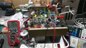
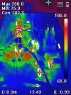
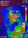
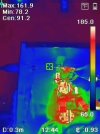
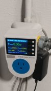
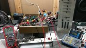
closer view of the approximated active circuit on the bench
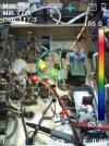
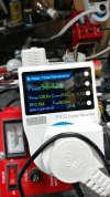
the cold-start relay+circuit has not been built yet. the top 270r 5w resistors emit around 240f/115c at idle and lower 100r 3w are comfortably less than that (didnt do a focused measurement on them).
front end triple zener is 160v x3 even though the sim has been update to a newer pending revision (comparing 500v vs 520v front end limiters). the 200-12k-200 for the back end limiter will be revised to 420v-440v range since this system will be dialed-in to handle 130v mains 24/7/365 or at least thats the design plan.
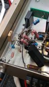
as you can see the inverted v-doubler has been replaced with series "film" cap feeding a bridge rectifier.
the 11+33 zener regulator will be replaced with either 47v or 51v 5w single. the zener's in the circuit have had their resistance specs matched to the data sheet. the sim normally uses a low level/blank template for diodes and various components. can change capacitor esr if needed.
the tube resistor equivalents have been adjusted so that the front-end / b+ / b1 sim numbers match bench tests (reverse engineering the sim for improved accuracy).
sim data file attached.
the story thus far, including roadmap for electron navigation
closer view of the approximated active circuit on the bench
the cold-start relay+circuit has not been built yet. the top 270r 5w resistors emit around 240f/115c at idle and lower 100r 3w are comfortably less than that (didnt do a focused measurement on them).
front end triple zener is 160v x3 even though the sim has been update to a newer pending revision (comparing 500v vs 520v front end limiters). the 200-12k-200 for the back end limiter will be revised to 420v-440v range since this system will be dialed-in to handle 130v mains 24/7/365 or at least thats the design plan.
as you can see the inverted v-doubler has been replaced with series "film" cap feeding a bridge rectifier.
the 11+33 zener regulator will be replaced with either 47v or 51v 5w single. the zener's in the circuit have had their resistance specs matched to the data sheet. the sim normally uses a low level/blank template for diodes and various components. can change capacitor esr if needed.
the tube resistor equivalents have been adjusted so that the front-end / b+ / b1 sim numbers match bench tests (reverse engineering the sim for improved accuracy).
sim data file attached.