• The move to the new server is done. There are some software and database maintenance updates in process. This has us passing the hat around to help out. We appreciate any donations. Seriously, even a dollar helps. The payment page may be found here - https://www.audiokarma.org/support.html
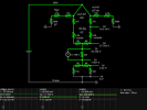
few words of caution about the above circuit, if built and powering the tube circuit.

due to the senselessly high ladder bias i started with, the bottle load is slow to wake up. which results in zener limiter stress (5w used each) for longer than desired. thermal camera helps to protect the situation and reduce any potential kaboom outcome.

the voltage-doubler front end is being used as a reducer/throttle due to the excessively high mains txf output. also notice that the circuit is only using half-tap of the high-tension secondary. series resistor with parallel cap on the v-doubler front end is a work in progress experiment which ultimately could be deleted down to a single cap on either rail (pre b+ and gnd).

the 1nf off of darlington base is variable up to around 100nf before output load ripple starts to be affected. initial design parameters were to be around 100uv RMS +/- 100uv or somewhere below 1mv RMS as an extreme starting point.

the newer/latest circuit version has more b+ and balanced load along with cold-start test slider. one easy solution for the slow heater wake-up is to use a time delay relay for the b+ circuit specifically. i havent figured out a capacitance throttle yet, using mosfet or igbt or vfet or something which would be quite useful. thermal feedback from zener limiter could also adjust the front end capacitance for a safe circuit design but havent made progress in that direction.

more starting point analysis needed but trying to refrain from feature creep, too many design options too soon, before stable v1.0 is achieved. its a work in progress type of thing.
 
why are you using a voltage doubler if the end result is under 300 volts? That seems like a needless amount of high voltage coupled with a high current demand on the transformer. Would make more sense to make this choke input, which will give you ~0.9x the AC input voltage rather than the ~1.4x that a full wave with a cap, or ~2x that a doubler provides.
 
doubler being used as a limiter that, when overloaded the b+ will sag or crash depending on the situation. i also noticed that the doubler-limiter doesnt need high capacitance caps. most everything in the front end will be below 1uf although should spec 700v or higher due to 485rms = 686peak. front end storage/filter/smoothing caps will obviously be higher than 1uf.

would be interesting to do some physics hacks with the choke but that will stretch the r&d timeline by way too much.
 
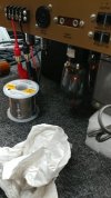
heathkit w5m - 21.jpg
the initial circuit design, measuring the front end after the v-doubler

heathkit w5m - 22.jpg
overall system is pulling low wattage, not surprising since the output cant play very loud.
 
needed to overhaul the bottle bias sim (6L6g flavor), not sure where i got the previous 188r number from though...

Screenshot 2026-06-27 at 14-22-23 6L6 bias - Circuit Simulator.png
current state of affairs with the recent testing data

obviously a far more competent tube sim like the tubeCAD stuff would be a better solution.


*john broskie

*copyright is a little out of date

**not the type of tube sim i am looking for, might be useful for someone else though
 

Attachments


kicking around the idea of a dual triode or tetrode/pentatode darlington capacitance multiplier. the npn in the current circuit will need to be mounted to a heat sink as will many high stress resistors.

might look into a diy smps design for better energy management and thermal comfort.
 
My concern here with the doubler, beyond just inefficiency throwing out so much voltage, is the current load on the transformer. Watts is watts, so double the voltage output and you get either half the available current, or you double the current load on the transformer.

under 300 volts is pretty much wasting a 6L6. 6V6 tubes would be more appropriate here. Better match for the transformer load too.
 
if i may clarify, watts is watts only when loading occurs.

by using what could be classified as an inverted doubler (x2 vs 1/2, times 2 vs one over 2) the excess high voltage is being ignored and only the amount allowed by a capacitance value is used hence how easy it is to brown-out the entire circuit if too much load is applied. think of it as a dim bulb limiter only instead of va/watt rating of the bulb we are using nano-farads of capacitance similar to a crossover tuning frequency. with 60hz being the target demographic for capacitive reactance, only so much is allowed though the front door instead of burning up a v-dropper resistor.

inefficiency, as it pertains to heat generation, tends to be the all too common norm with class-a and/or tube designs. its idling at full throttle or close to it even when zero signal is in attendance. an example, all the house lights are on and the electric: oven + furnace + laundry + water heater + any appliance large or small 24/7/365 even if nobody is home to utilize or enjoy any of it. especially the utility bill every month.

my initial design target of 286v b+ is proving to be more than just half-baked. have yet to find a suitable photo of half a donkey for this project. and then there is the all too common question of free range fully organic donkey vs gmo donkey or even going with fully synthetic burro to reduce oil change intervals and better viscosity rating.

*yes, i totally went there and took pictures

the overall potential of the mains txf is indeed being neglected since the bulk of it isnt needed. higher efficiency from wasting less energy might be counter intuitive for an amp design that is naturally wasteful, i realize the output-iron-y of the project.


a trip down theory/calc memory lane that i also will benefit from.
 
heathkit w5m - 23.jpg
lights are on and somebody is definitely home. kick some tires and not light some fires if possible (magic smoke = expensive party and cleaning bill).

heathkit w5m - 24.jpg
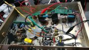
its a mess and the old/initial design plus ill-fated 330+1k//1k+330 ladder is shown. an example of how to turn a ~20w amp into a ~4w amp, with low idle wattage (somewhere around 30w).
 
-- fast forward --
most recent testing and circuit revision is sitting at:
383v up front
360v/npn/346v
324v b+
311v b1
-65 b- (heater offset, too high: need to redesign for 48v).

currently with the 4.7k screen tap resistors there is a ~7v drop indicating 1.489ma flow.

with the higher output using 470nf/220r/220nf inverted v-doubler front row and output bias ladder at cat>68>510r 7w//510r 7w>68>pot the system has obviously better output punch. thermals definitely showing some concerns due to limited selection of high wattage components near the bench, hello revised shopping list. even the darlington (without heat sink) is getting too hot and needs improved protection to move forward.

when calculating 100ma of b+ flow its easy to calculate how even the lowest source of resistance is going to get hot. revised b+ target looking to be around 350v or high as 400v depending on zener limiter final numbers. cold power up will certainly benefit from a 100nf strapped 600v relay for a two step quantum dance procedure.
 
i suppose b- is a term reserved for the -voltage supply of a fixed bias system. so would b1- be more appropriate for heater/filament dc offset terminology?
 
C- is bias supply to the grids, C+ is 0v / ground. B- is also ground / zero volts. B+1, B+2, etc is typical for the various supply voltages, or just call it out by voltage. +400v, +300v, etc. A would be filaments.

honestly nobody uses A or C anymore, its ancient stuff from the days of battery supplies. No clue why B stuck around.
 
from an alphabetical order view of priority voltages it makes sense.

a = filament/heater, if there is no heat then there is no circuit load and nothing happens
b = battery = dc, no idea if using the word battery was preferable in the early 1900's vs saying direct current
c = bias/grids, seems slightly out of order since if the grids have an issue it will be instant game over (red plate)
*although diode has no grid and was invented before triode
**"b" = battery also misleading since all three designations are batteries

*"a" battery, "b" battery, "c" battery


after looking through the first link, everything is a battery designation. so the view of what battery is 1st/2nd/3rd must have been gradual from light bulb to diode to triode and beyond. either way, interesting vintage jargon to revisit.


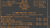
revisiting the 6L6g data sheet, noticed a few more things of design concern (amp circuit).

Screenshot 2026-06-28 at 00-57-13 6L6 6L6G - 6L6.pdf.png
max heater to cathode tolerance for the outputs is suitably healthy, good to see

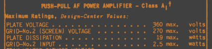
Screenshot 2026-06-28 at 01-00-26 6L6 6L6G - 6L6.pdf.png
grid-2 voltage max regardless of amp class

interesting to note with fixed bias, negative grid supply, the are ratings for zero signal and max signal. which gives the motor room to rev higher vs idle. that explains a few things in regards to output wattage reserve before distortion kicks in (tube magic).

after circuit version 1.0 is complete with cathode bias test bed, upgrading to fixed bias for v2.0 should be interesting after 1.0 is demo room tested for a while.

i suppose optimal wattage and performance spec valve for this amp looks to be the 7027a as noted in dcg-designs thread.


*original rca data

also, 6L6 type of bulbs seem to have a lower heater amperage which is also beneficial to mains-txf health and longevity.

kt66: 1.3a + 1.3a
vs
6L6: 0.9a +0.9a
 
heathkit w5m - 25.jpg
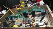
better view of the first batch of r&d updates. plus figuring out front end capacitance values, the joy of trial & error + rinse & repeat.

the 5v tap is capped with tape (not used yet) and the other side of ht secondary has a wire nut hat (not used). on the original schematic there are three "g" 20uf 450v caps (multi cap tower, topside) which have been replaced with three 1uf 630v film caps.

sooner or later this will be a 100% film cap zone, no electrolytics allowed. not even for a timer circuit.

heathkit w5m - 26.jpg
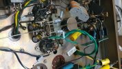
after changing the over-sized bias ladder resistors to something less restrictive. also heater resistor cameo (0.22r 5w)

cat > 68r > 510r 7w//510r 7w > 68r > pot

blue body resistors are 2w flameproof, selected for their wattage and under 100r. whatever components are near the bench is the biggest limitation vs constantly ordering "what if" values which gets expensive.
 
need to sort through current/new batch of photo notes to be posted.

also fine tuning the sim schematic layout and parts count for a closer attempt at achieving v1.0 stable test bed. interesting to note that deleting the npn filter and doing the usual crc layout bumps the b+ ripple up to around 50mv vs ~100uv with the npn circuit (sim numbers). trying to keep the voltage drop across the npn to 8v or less since it heats up noticeably around 10-12v and higher.

the npn could get a jacket style heat sink or compress it against the metal chassis but high voltage insulation/isolation can be problematic in the long run. running the npn hotter with a heat sink still stresses the junction with high temp.

screen g2 resistors are 220r 2w even though that was short lived and updated to 4.7k which may get bumped up to 47k to create 70v drop. after revisiting the 6L6g data need to be mindful of the 270v max rating and 19w limit for the anode/plate.

relay circuit and timer still need to be constructed, parts shopping as well.
 

perhaps a closer look at what the screen grid (g2) should be doing and how much current/milli-amp activity should be expected.
 
you don't need the plate supply to be ripple free in a push-pull amp. It goes in common mode and cancels.

47K as a screen resistor supply would be a bad idea. that would be the place to use a regulator to drop things if you want one in here. Depends on the particulars what the shift in current would be but anywhere from 50-300% depending on operating mode and loading would be typical. Its enough under any arrangement that high value resistive droppers work very poorly, even with the shunt load of the front end tubes added in to reduce the swing from min to max.

1782737276067.png
 
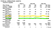
doing calculations for rg2 based on zero and max from the table above would be:
47k at 3.5-11ma = 164.5-517v drop
33k = 115.5-363v drop

definitely a moving target although a 1k value would be 3.5v-11v variance and the currently installed (no test drive yet) 4.7k with the above parameters would be 16.45v-51.7v which seems suitable to some extent. having g2 react with signal level including out-txf inductance vs hard limited to a b2+ supply might be an interesting sonic/output comparison. should be easy to monitor rg2 voltage drop with a signal generator source to see how much the system reacts, in terms of g2 milli-amp swing.


*page 3, interesting data
 
screen dropping by a factor of 3 is really bad for performance. The current flow through the tube is significantly impacted by that voltage changing. Some amps did have the screen drop that much, but those can be significantly improved by tightening up the supply. Even the old texts will talk about regulating the screen supply with shunt regulation or use of gas regulator tubes. Better amps and commercial gear did it that way, but lots of consumer stuff did not.
 
Back
Top Bottom