• The move to the new server is done. There are some software and database maintenance updates in process. This has us passing the hat around to help out. We appreciate any donations. Seriously, even a dollar helps. The payment page may be found here - https://www.audiokarma.org/support.html
The 6L6, 6L6G, 6L6GB do not and should absolutely not be used here.
i wonder how much damage the previous owner inflicted upon the amps, unknowingly, since both mono's have 6L6g outputs. no idea how many hours or detailed history. other than the mains-txf needing rebuild/rewind and most things inside the chassis being original.
 
i wonder how much damage the previous owner inflicted upon the amps, unknowingly, since both mono's have 6L6g outputs. no idea how many hours or detailed history. other than the mains-txf needing rebuild/rewind and most things inside the chassis being original.

Maybe he got lucky. Or maybe it was never even used with 6L6Gs and someone stuck them in the already broken amplifier, so they could snatch the valuable KT66s and make it look better for sale. Can speculate anything but one thing is for sure, the 270V screen rating and 19W plate limit of the 6L6G are fundamentally incompatible with proper and reliable operation of a W5M.
 
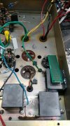
heathkit w5m - 60.jpg
a somewhat more up to date photo of current project process, self-inflicted slog...

figuring out placement and mounting of the new parts, thick film resistors mounted to chassis preexisting bolt options (the challenge of limited options).

and whether or not to use the green boards as connection consolidation lily pads (green not gilded) form factor or just run a bunch of wiring to jumper various connections. might have to invest in liquid electrical tape or corona dope since resistor legs are rather close to the chassis ground plane. maybe some transistor mica pads will be sufficient for 250r upper (pre b+).


*membrane repair product also looks interesting

temp rating of products might be a concern, 220f/104c.
 
but one thing is for sure, the 270V screen rating and 19W plate limit of the 6L6G are fundamentally incompatible with proper and reliable operation of a W5M.
incompatible and most likely higher than average kaboom potential.

from what the current owner has said, the amps where offered to him for sale and they were demo'd for a while and then at some point the mains txf showed its age and limitations. should probably have one of the local tube addicts test the 6L6g's for strength and estimate remaining lifespan.
 
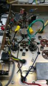
heathkit w5m - 61.jpg
figuring out the new layout is going to be a headache plus the diy relay timer board layout

250r 35w near the middle of the chassis and 100r 35w closer to the film caps and rectifier socket.
 
incompatible and most likely higher than average kaboom potential.

from what the current owner has said, the amps where offered to him for sale and they were demo'd for a while and then at some point the mains txf showed its age and limitations. should probably have one of the local tube addicts test the 6L6g's for strength and estimate remaining lifespan.

Some early 50s amps did abuse the ratings of the 6L6G and still managed to work, but in this case it seems a little too far.

View attachment 3801129
figuring out the new layout is going to be a headache plus the diy relay timer board layout

250r 35w near the middle of the chassis and 100r 35w closer to the film caps and rectifier socket.

Might want to check the voltage rating of those TO-220 resistors. They look a little close for comfort to me. I stuck with ceramic wire wound so I could keep them away from the chassis and anything metal.
 
it would appear that sqrt(35*250) is a very small number indeed. eyes must have locked onto 2kv ac and called it a day.

the relay timer circuit is also proving to have some issues, oddly enough math related. starting to see a trend here and scrap status for the overall project attempt is lurching ever closer. even after a few ugly-circuit sonic demo's that showed decent performance.

after seeing the limited mounting options will need to go in a different direction with a few things. since the pre b+ resistors need something better and the other locations (b- at 100r 35w, a+ at 0.20r 35w, bias core at 250r 35w) will be much closer to 100v or less (still useful), more parts shopping needed with a side order of punch to the face (for designer/shopper).

so a pair of 250r power resistors and few other miscellaneous items will be on the list. should also update the 555 schematic to include 1n4148 across the relay, in case of coil kickback even though none was measured (dmm min/max mode).

 
unless... full rated voltage is only from the perspective of voltage drop across the resistor and not how much voltage the circuit applies to it. an example being: 600v 0.1a circuit constant more or less and r*i for the v-drop being 25v which equates to 2.5w of thermal stress.

the 2kv dielectric/safety rating would be a max design limit regardless if 1ma or 10ma is constant from circuit requirement. probably how i initially perceived the numbers and equation. in that scenario the selected components are fine.
 
it would appear that sqrt(35*250) is a very small number indeed. eyes must have locked onto 2kv ac and called it a day.

the relay timer circuit is also proving to have some issues, oddly enough math related. starting to see a trend here and scrap status for the overall project attempt is lurching ever closer. even after a few ugly-circuit sonic demo's that showed decent performance.

after seeing the limited mounting options will need to go in a different direction with a few things. since the pre b+ resistors need something better and the other locations (b- at 100r 35w, a+ at 0.20r 35w, bias core at 250r 35w) will be much closer to 100v or less (still useful), more parts shopping needed with a side order of punch to the face (for designer/shopper).

so a pair of 250r power resistors and few other miscellaneous items will be on the list. should also update the 555 schematic to include 1n4148 across the relay, in case of coil kickback even though none was measured (dmm min/max mode).

Here's how I did my rebuild. Don't scrap the project, it's worth getting to the finish line.

Flyback diodes are always a good idea
 

Attachments

  • 20251226_170328.jpg
    20251226_170328.jpg
    133.6 KB · Views: 6
the 2kv dielectric/safety rating would be a max design limit regardless

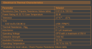
It isn't clear if this is a value it is tested to, or if it is fine to operate at such a high voltage. One thing is for sure, the proximity of the leads to the metal tab on a TO-220 make me question if operating at such a high voltage is a good idea.
 
Yeah I wouldn't trust DMM min/max mode to reveal relay flyback. Need a scope for that. Also I agree with @maxhifi that operating voltage is the relevant spec here for the resistor. It explicitly says 250 volts maximum OR limited by ohm's law. Dielectric tests are done with a hipot tester and not equivalent to a constant DC voltage rating. It's more like what the part can temporarily withstand under some transient failure condition.
 

since the dielectric of air is around 3kv per mm, although the voltage doesnt seem to scale in a linear fashion vs distance, just need to make sure a 1kv rated safety distance is observed. plus add some safety margin, corona dope or something, to improve most what-if scenarios.

your build photo looks nice, clean and tidy overall circuit layout.

A decent oversized mica insulator under the resistor with some heat sink compound would probably be nice. Although I do question the ability of the steel chassis to conduct heat. Aluminum is so much better.

It isn't so much just the air part that I'm worried about, but possible breakdown of whatever is insulating the tab from the resistor element inside the package. I concur with @AlexHempel that 2kV is likely a hipot test and not an operating voltage. Or at least I will say that if something is unclear and there's two possible interpretations, I will take the more conservative one without better information being available.

I'm really happy with my builds. The only issue I've had is one of the original Mullard 12AU7 tubes was noisy. I used to prefer "minimal" rebuilds where I would only replace faulty components and leave the old carbon resistors in place. These days I just don't want to be bothered with repeated repairs and out of spec equipment so I change them all.
 
* 25w package rated for 520v

*ohmite, mouser tracking of product page hits is rather annoying hence no direct product link in this post.

after spending time with a hipot test fixture (high-potential) in the high power ac/dc motor controls industry (around 2 decades ago) it is interesting to see a corona form. although it does require a low light environment to see the faint purple-ish glow. i should have made note of make & model of test fixture since it was sensible sized and reasonably capable (ac and dc testing).
 
Although I do question the ability of the steel chassis to conduct heat. Aluminum is so much better.
chassis steel vs aluminum thermal dissipation, also a good thought.

in terms of thermal intensity it will be around 1-1.5w for the 100r and 2-3w for the 250r. bias core will no doubt be higher, possibly 2.5-3.5w depending on how close to 100ma to feed both output cathodes. for a+ safety padding it will be 1.25-1.5w depending on output bulb heater rating.
 
excellent question. one thing that stood out was... heater offset strategy.

the numbers selected paint an interesting picture.
meaning the heater elevation setup to set heater-cathode voltages?

stock per the manual when not used with a preamp, the center tap of the heater winding goes to ground, so 0v. Worst-case H-K voltage will be at the phase inverter, the cathode sits at 100v per the manual. KT66 cathodes are at 50v, the other 12au7 sections are listed at 13 and 2.2v. H-K limit on a 12a*7 is 100v so technically within limits but barely. It will definitely be inclined to hum issues caused by heater insulation failure at that stage, or generally poor performance if it starts leaking cathode to heater/ground. I had that problem with bad 7199 tubes in a Dyna ST-70 once. No hum, it just made poor output because a significant amount of the signal from the cathode side of the inverter just dumped to ground instead of the output tube grid.

In the modified, the heater is elevated by about 80v, which puts the inverter +20 H-K, the output tubes -30, and the other tubes at -67 and -78 respectively. Ideally you want the heater positive vs the cathode to minimize noise, but thats not possible to do and keep within limits for the other tubes. I suppose 80v was chosen as a practical compromise to minimize voltage difference at the splitter without exceeding anything else.
 
meaning the heater elevation setup to set heater-cathode voltages?
correct

In the modified, the heater is elevated by about 80v, which puts the inverter +20 H-K, the output tubes -30, and the other tubes at -67 and -78 respectively.
it seemed odd to have such a high modified offset to appease one of the four triodes up front (v1/v2). which ultimately pushes two others closer to the noise/kill zone/limit. part of the reason why i started focusing on 48-51v zener was to try and make sure all the triodes are away from their max limit not just one. a small gripe but it was the first numerical oddity that didnt sit right with me.

thank you for putting the keyboard effort into investigating the situation from an experienced point of view. another design "consideration" for others to think about. it might be a trivial, can barely hear a difference, type of thing but heaters love to inject noise.
 
Back
Top Bottom