• The move to the new server is done. There are some software and database maintenance updates in process. This has us passing the hat around to help out. We appreciate any donations. Seriously, even a dollar helps. The payment page may be found here - https://www.audiokarma.org/support.html
correct


it seemed odd to have such a high modified offset to appease one of the four triodes up front (v1/v2). which ultimately pushes two others closer to the noise/kill zone/limit. part of the reason why i started focusing on 48-51v zener was to try and make sure all the triodes are away from their max limit not just one. a small gripe but it was the first numerical oddity that didnt sit right with me.

thank you for putting the keyboard effort into investigating the situation from an experienced point of view. another design "consideration" for others to think about. it might be a trivial, can barely hear a difference, type of thing but heaters love to inject noise.

Having the heater elevated relative to the cathode helps to reduce hum. This is a very old and well known fact, with RCA PA amplifiers going back to the 1940s having the heaters elevated via a resistor voltage divider off the main power supply. It is usually done for preamps though, the signal levels in a power amplifier are so high that hum from the cathode is less of an issue.

I think what Dave did makes technical sense, although I questioned its necessity due to the fact that there is no track record of 12AU7 heater to cathode failures in Williamson derived amplifiers. I didn't implement it in mine simply because of this, although it sure cannot hurt. It's going to be the same issue in any direct coupled tube amplifier.
 
*page 2, about half way down


4500v/mil should be adequate, times a 3 mil product thickness.

Yes absolutely. Just need to also make sure to use an insulated bushing for the screw, or forget the screw and clamp it down.
 
A common way of doing elevated heater supplies is to tie the center tap, real or fake, to the output tube cathodes when they are cathode biased. Thats a free source of DC that requires no other components.

Can't speak to failure rates, or what other specific Williamsons may run for voltages on the inverter but i have had leaky split load and long tail pair triodes in other things.
 
heathkit w5m - 63.jpg
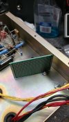
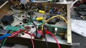
recycling one of the chassis mount component junctions to function as a mounting solution.

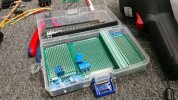
board will contain relay//68nf and 555 timer circuit plus 5v txf tap landing zone.
 
heathkit w5m - 65.jpg
cleaning up more space and reorganizing a few things especially around the bias ladder. a mock up mounting of things to better evaluate what can go where and why. the v1/v2 area still needs to be cleaned up after adjusting some values.

interesting to note, when the cathode bias resistor value decreases the bypass cap effectiveness also trends downward. using a 100uf or 220uf would be the most extreme reduction of impedance and yet how much resistance is noticeably from an amplitude perspective since resistors dont care about frequency until ~100k and beyond (estimated).

resistance can effect the highs like 10k-20k which is crucial for detail and spacial awareness as it pertains to echo location / acoustics of the recording but... how much is too much. a simple high grade 100nf cap between phase splitter and output can make a world of difference provided the speakers being used and human hearing present can send & receive accurately.
 
heathkit w5m - 66.jpg
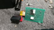
preparing component layout i.e. climbing another mountain

14-pin chip socket might get trimmed down to 8-pin for the 555 timer chip. easier to leave it as-is for now.
 
heathkit w5m - 67.jpg
adjusting large component placement as the circuit is built. wonder if the relay diode is close enough to the coil terminals, practically sitting on top of them.

some "x" safety caps are inbound for the final circuit build.
 
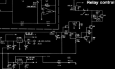
another thought that i am starting to evaluate is borrowing a circuit chapter from apt holman preamp (relay control circuit).

Apt-Holman-Schematic preamp beautiful invert relay.png

the full high resolution schematic was chopped down to the relevant portion. one nice thing about this circuit is that the after-latch throttle down of holding voltage (less coil heating effect).

season-1 had a brief throw down with the preamp's not-so-great/weak rectifier design. also another site has indicated undersized mains txf.
 
some informative links about the preamp. if i am going to hijack my own thread may as well go all the way...


the preamp circuit chunk could possibly replace the 555 timer headache to help simplify the overall design.

with the currently 40nf relay bypass b+ warm-up/soft-start design (bumping up to 68nf x cap, maybe 100nf) it is possible to siphon some electrons for a regulated rc timer circuit to fire off the relay. would need to average out the regulator circuit to handle 110v mains minimum and up to 132v mains for extreme durability.

more cooking time in the circuit sim, starting to run low on avocado oil and onion powder.
 
heathkit w5m - 68.jpg
continuing forward with the ill fated 5v txf tap feeding a bridge rectifier and then into a dc2dc boost regulator. nope, not going to work as needed. another approach will be pieced together.

using the 5v tap in series with the 6.3v tap works fine except who knows how much noise is being injected into the already sensitive heater circuit. probably not a good idea either way.

connecting to the main b1 feed is possible but the scaling down to regulated 12v will require too many parts and high temps.
 
heathkit w5m - 72.jpg
for reference, the cheap multi-pack of plated boards being used for this project. from the usual source amzn or wherever.

heathkit w5m - 69.jpg
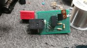
attempting a low voltage test (heater tap and 5v tap connected) of the timing circuit, monitoring relay toggle from normally open contact to closed.

due to the voltage drop from the bridge rectifier the 5v tap didnt have enough voltage to satisfy the minimum needed for the dc2dc regulator. not to mention a moderate sized filter circuit will be needed after the regulator. so the overall design is being overhauled again.
 
after running a few more "what if" circuit sims there is a brute force option vs using a soft-start timer relay design. bumping up the zener shunt regulator (3 zener's in series) into 3 ranks. two ranks are being used currently as an over-shoot/surge safety net which could be deleted completely due to the timed relay (130v mains might require the front triple for over-kill safety of 600v caps).

across each 30uf filter cap use a 5w triple-z creating three strings of three or 15w to compensate for the voltage slam/surge on a cold start (or warm start) from the step-down mains film cap. using a 680k 5w in parallel for each 30uf section also advised to help bleed excess over-voltage (5w resistors are cheap and robust).

depending on c-r-c resistor values, either [250r over 100r] or [300r over 250r] or [300r over 100r] will influence what zener values should be used to balance out the thermal countermeasure, an example being 180+160+180 (520v shunt).
 
in the above sim, yuck more typing...

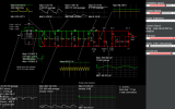
the output tube load is open (circuit switch toggle) and the 1k rc value (1k 7uf) is bumped up to cold load status. overall showing hypothetical zener wattage/stress to be expected. for 5w zeners it would be best to dial things down to 2.5w even though that is still extremely hot to endure a ~5s timeline before the circuit load wakes up.

another mod would be to change the 1k/7uf into the previously tested npn filter to improve things by a couple orders of magnitude, 10-30mv ripple down to under 100uv ripple. just a thought, no idea how any of this will affect on/off power pulse via woofer movement.

creating a simple module that can be replicated three times seems easy enough (680k 5w / 30uf 600v / z+z+z) and then use simple 10w or 25w power resistor (cement type?) for the b+/b- interconnect i.e. minimal 600v hookup wire needed (copper is getting expensive).

prefab the end b1 module for multi-node output. job done...
 
the current and above described circuit designs no longer qualify for bce designation (bean counter edition), way too many parts being used.
 
What are you trying to do with the power supply? The full wave bridge rectifier is a little weird to see. Is that just a simulation thing?
 
Back
Top Bottom