

You are using an out of date browser. It may not display this or other websites correctly.
You should upgrade or use an alternative browser.
You should upgrade or use an alternative browser.
heathkit w-5m renovations [boondoggle edition] quantum vacuum deep dive
- Thread starter sae-7125
- Start date


You have one too many diodes in your sim. The center tap is ground / B-. No diode. Unless you're planning on back-biasing things you don't want a resistor between the CT and ground either.
The end windings are only loaded at a 50% duty cycle, the center tap is flowing all the time so double the current is to be expected.
the series caps in the high voltage supply is the work-around for the high turn-on voltage. Or single very high voltage caps will do it too but imagine for a moment that its 1959 and you're designing things to a reasonable price point. Two off the shelf caps in series is a lot more practical than one special high voltage cap. We have some more options now but past about 500v with any sort of reasonably high capacity value it still gets pretty thin.
if this runs in AB, you want the least series resistance between the output tubes and the output of the power supply as possible otherwise the voltages will sag considerably. If losing some voltage is absolutely needed, a resistor bypassed with a zener diode between transformer center tap and ground will do it. Size it so the resistor carries most of the load at idle to allow the zener as easy a life as possible. You can use this as a negative grid bias supply instead of cathode bias too, just tie things to the transformer CT as the negative voltage source. Class A operation doesn't care very much, the current demands are basically flat from idle to full output.
The end windings are only loaded at a 50% duty cycle, the center tap is flowing all the time so double the current is to be expected.
the series caps in the high voltage supply is the work-around for the high turn-on voltage. Or single very high voltage caps will do it too but imagine for a moment that its 1959 and you're designing things to a reasonable price point. Two off the shelf caps in series is a lot more practical than one special high voltage cap. We have some more options now but past about 500v with any sort of reasonably high capacity value it still gets pretty thin.
if this runs in AB, you want the least series resistance between the output tubes and the output of the power supply as possible otherwise the voltages will sag considerably. If losing some voltage is absolutely needed, a resistor bypassed with a zener diode between transformer center tap and ground will do it. Size it so the resistor carries most of the load at idle to allow the zener as easy a life as possible. You can use this as a negative grid bias supply instead of cathode bias too, just tie things to the transformer CT as the negative voltage source. Class A operation doesn't care very much, the current demands are basically flat from idle to full output.

maxhifi
Addicted Member
To add to what gadget said above
1. The current at the CT is the sum of the current in each coil. Inside the transformer there are two wires connected to the CT and the current is divided between them, so nothing is overloaded. You're just simulating how this circuit is expected to work.
If your simulation shows that the bridge rectifier draws less power than the full wave rectifier, it's probably because there are more losses in the circuit and the voltage is lower. I suggest taking some time to understand how the circuit works before relying too heavily on simulations, because the simulation seems to be leading you to conclusions that could be harmful to the objectives of the project - i.e. a reliable amplifier.
2. Why have you added a third diode?
3. Correct, you need more than a 1000V diode rating. I suggested two or even three 1000V rated diodes in series for each diode shown in the schemaric.
4. For the 6AU4, the tube is not really designed for this use so the data sheet isn't too useful. It can however be use successfully. I used a pair of 19AU4 as rectifiers in a stereo amplifier I built in 1998, and although the output tubes have been changed 4 or 5 times since then, the rectifiers are still the same ones I installed in 1998. Expect a 10-20 volt drop, and fine tune it by adjusting the resistor values after the amplifier is constructed.
1. The current at the CT is the sum of the current in each coil. Inside the transformer there are two wires connected to the CT and the current is divided between them, so nothing is overloaded. You're just simulating how this circuit is expected to work.
If your simulation shows that the bridge rectifier draws less power than the full wave rectifier, it's probably because there are more losses in the circuit and the voltage is lower. I suggest taking some time to understand how the circuit works before relying too heavily on simulations, because the simulation seems to be leading you to conclusions that could be harmful to the objectives of the project - i.e. a reliable amplifier.
2. Why have you added a third diode?
3. Correct, you need more than a 1000V diode rating. I suggested two or even three 1000V rated diodes in series for each diode shown in the schemaric.
4. For the 6AU4, the tube is not really designed for this use so the data sheet isn't too useful. It can however be use successfully. I used a pair of 19AU4 as rectifiers in a stereo amplifier I built in 1998, and although the output tubes have been changed 4 or 5 times since then, the rectifiers are still the same ones I installed in 1998. Expect a 10-20 volt drop, and fine tune it by adjusting the resistor values after the amplifier is constructed.
Last edited:

sae-7125
Super Member
correct, i was curious to see how the sim responds vs without the diode.You have one too many diodes in your sim. The center tap is ground / B-. No diode.
good pointUnless you're planning on back-biasing things you don't want a resistor between the CT and ground either.
The end windings are only loaded at a 50% duty cycle, the center tap is flowing all the time so double the current is to be expected.
both correct and accurate, my overload concern is in reference to possible txf manufacturing flaws. which typically are found after decades of use out in the field. i seem to recall the current owner mentioning something about a center tap issue which is why both mains txf's were sent to heyboer for rebuild/rewind.The current at the CT is the sum of the current in each coil. Inside the transformer there are two wires connected to the CT and the current is divided between them, so nothing is overloaded.
sae-7125
Super Member
definitely something to remember when evaluating vintage systems/design. and now its the future where we have the technology to make things better and lost longer, at the same time. truly a wonder thing, going from 70 years to still being functional after 100 years i.e. 2055 is going to happen regardless.but imagine for a moment that its 1959 and you're designing things to a reasonable price point.
it nice to see film cap options as well for the 800v arena. perhaps designing the full tap version front end for 650v instead of trying to regulate at or below 500v would be a suitable alternative. would need to bump up some resistor values including bias core and cathode bypass caps to compensate.We have some more options now but past about 500v with any sort of reasonably high capacity value it still gets pretty thin.
if this runs in AB, you want the least series resistance between the output tubes and the output of the power supply
good design notes to consider.Class A operation doesn't care very much, the current demands are basically flat from idle to full output.
sae-7125
Super Member
most likely not an ideal apples-to-apples power consumption comparison but it highlights potential limitations either way.If your simulation shows that the bridge rectifier draws less power than the full wave rectifier, it's probably because there are more losses in the circuit and the voltage is lower.
i am starting to notice that as well. example circuits in/on a spec sheet can be helpful if they exist in the first place.For the 6AU4, the tube is not really designed for this use so the data sheet isn't too useful.
good design info for future reference.Expect a 10-20 volt drop, and fine tune it by adjusting the resistor values after the amplifier is constructed.
the beauty of a circuit sim is there are usually fewer parts on fire and any mess is relatively easy to cleanup. understanding why the mess occurred, thats a different brain dept which should be consulted from multiple points of view (audio forum shall do nicely).
soon as the circuit is built and bench testing occurs, thats when the real designing begins. electron reality is a harsh mistress vs any level of theory contained in a book (or not i.e. improv engineering).
inputting voltage measurements from the bench into the sim helps to reverse engineer the design (sim calibration with reality). understanding will always be lacking hence the existence of the project and an amp owner who is curious to see/hear what i come up with.
random update: the test bench hasnt caught fire yet.

sae-7125
Super Member

after adjusting the full-tap mod, there might be some build potential and simplicity (no timer circuit).
currently showing inrush with the first 55ms although this is not cold start accurate. toggle the b+ output resistor switch to see overload/surge approximation and circuit stress.
in term of parts:
20uf 1kv film x2 for the front end (fresh parts order needed)
30uf 600v film x2 for b+ and b1 nodes (already have those near the bench)
z-shunt = 200/160/200 5w each to protect 600v caps and all glassware
the 100/50/100 resistors off of the ht tap should help buffer some of the inrush+daily stress/abuse not to mention pad the first rc filter rung/node/whatever. either 5w or 7w for the 100r and then x2 in parallel for the 50r. the first 100r connected to 20uf idles around 3.2w while the 300r after it settles at 3w so resistor wattage value for the 100r should be high, possibly chassis mount like the 300's will be. the b- 100r could be 10w non-chassis mount or low as 5w maybe.
using 1uf 350v or 450v for g2 z-reg circuit (not shown) and a+ offset are of unknown benefit if any.

clearer view of the circuit, previously posted snapshots look blurry and terrible.
the tapped txf in the sim is programmed with 150mh primary and 0.1237 sim ratio which equals [ratio 1 : 8.084] and produces 650v dc nominal when rectified. the pair of rectifier diodes are silicon and should be rated for 3a 1200-1500v. another reason i am not focusing too much on using a flavorful tube rectifier is reducing 10-15w of stress on the mains txf core. just like with using 0.9a heater rated outputs vs 1.3a kt66 norm, every little bit extends txf life unless there is another major flaw getting exploited.
wont know how bad things are unless the circuit gets built and bench tested, sims are crude approximations at best. maybe for the next pair of "proof of concept" w-5m's since the current owner is on the lookout for more.
still need to calculate output load equivalent (bias sim will help).
sim data attached.
**the gz34/other and 6au4 design ideas are still on the table and in play, not shelved.**
Attachments
sae-7125
Super Member
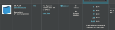
an example of a hard to damage component spec
it will end up being the same total current in the transformer regardless of configuration. Its either all of the current through 1/2 the secondary, or 1/2 the current through each half of the secondary. If its overloaded in stock config, its more so when using only half of it. I guess maybe you might get lucky and be able to use the other half if it burns out again but thats a gamble.both correct and accurate, my overload concern is in reference to possible txf manufacturing flaws. which typically are found after decades of use out in the field. i seem to recall the current owner mentioning something about a center tap issue which is why both mains txf's were sent to heyboer for rebuild/rewind.
single high voltage caps are fine, so long as they are rated to deal with the voltage. Series electrolytic was the only practical option when this was made.
sae-7125
Super Member
Kirchhoff's circuit laws - Wikipedia
maxhifi
Addicted Member
a casual thought, it would be interesting to find out what the actual mains txf rating is suppose to be (va or watts, i'm not picky). as well as what the core saturation limit is for each half of the ht secondary (ampacity, how much load should it handle).
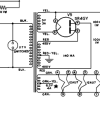
Looks to me like (15*3 = 15W) + (6.3*4 = 25.2W) + (455*0.140 =63.7W) = 103.9W
So, why did I only use half the high voltage winding, and not the full winding, in the above calculation? Because each half only has a 50% duty cycle, they're used alternately, but never loaded at the same time, due to the rectifier's switching action.
If we were to use only half the high voltage winding with a bridge, although the overall load on the core and primary would remain the same, the (i^2)* R losses in the used half of the winding increase due to the doubling of RMS current through that winding, which would increase the temperature of the winding, possibly (likely) beyond the insulation temperature limit.
sae-7125
Super Member
www.diyaudio.com/community/threads/using-half-of-a-center-tapped-winding.257435/
post #11 mentions something about 71%, most likely 0.707 rounded up. suppose i should contact a txf manufacturer for ct design limits and the joys of vintage spec iron.
www.audiokarma.org/forums/threads/heathkit-w-5m-power-transformer-question.498711/
posts 6 and 14 paint an interesting picture especially on how to handle a problematic factory txf design.
post #11 mentions something about 71%, most likely 0.707 rounded up. suppose i should contact a txf manufacturer for ct design limits and the joys of vintage spec iron.
www.audiokarma.org/forums/threads/heathkit-w-5m-power-transformer-question.498711/
posts 6 and 14 paint an interesting picture especially on how to handle a problematic factory txf design.
sae-7125
Super Member


sae-7125
Super Member

using jumper wires when testing 5v + 6.3v txf taps in series. decided against it due to noise injection concerns, possibility of vs actual amp performance measurements.

trying a different location for the relay+timer board. 5v tap now terminated with heat shrink socks (open circuit).
sae-7125
Super Member

bias ladder numbers vs bypass cap xc:
factory cathode/bias/pot/b-
30--330--100//100--150//150 = 30+330+50+75 = 485r per output
active test mod
24--250--24//24--150//150 = 24+250+12+75 = 361r
xc (cap reactance) at 30hz
100uf = 53.05r
47. uf = 112.88r
22. uf = 241.14r
10. uf = 530.52r
4.7 uf = 1.13k
1.0 uf = 5.31k
factory 485r//100uf = 47.82r
mod 361r/47uf = 85.99r
mod 361r/10uf = 214.82r
mod 311r/47uf = 82.82r (ladder core 250r//1k = 200r)
Capacitor Reactance Calculator - Free Online Xc Calculator
Calculate capacitive reactance (Xc) instantly. Understand capacitor behavior in AC circuits with live visualization.

Parallel Resistor Calculator - Engineering Calculators & Tools
Calculate the equivalent resistance of up to six resistors in parallel with ease while learning how to calculate resistance in parallel and the parallel resistance formula.
 www.allaboutcircuits.com
since the 16309 out-txf gets into trouble below 30hz, will be focusing on protective slope below 35hz. might help with reducing any amount of power-off woofer pop as well (unknown, more testing needed).
shopping for 33uf 63v or 100v film cap is a possibility.

