

You are using an out of date browser. It may not display this or other websites correctly.
You should upgrade or use an alternative browser.
You should upgrade or use an alternative browser.
heathkit w-5m renovations [boondoggle edition] quantum vacuum deep dive
- Thread starter sae-7125
- Start date



sae-7125
Super Member
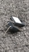
looks like a pair of 120k in parallel would improve things.
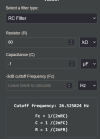
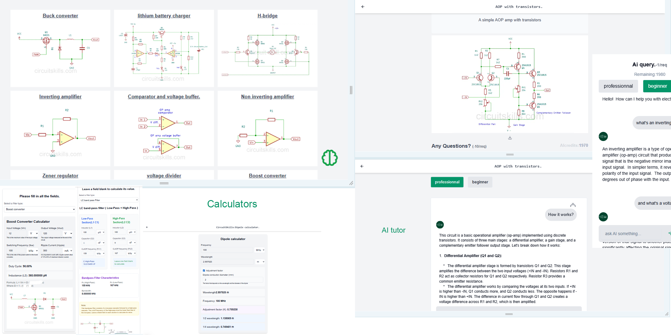
 www.circuitskill.com
CircuitSkill - Filter calculator |RC|LC|RL: Engineering Calculator & Tools
RC, RL, and LC Filter Calculator. Design and analyze Band-Pass, Low-Pass, and High-Pass filters, including cutoff frequency, bandwidth, and response characteristics.
www.circuitskill.com

sae-7125
Super Member

www.youtube.com/watch?v=TvQWX0M6hJY
key points of interest, my searching for basic info, are at 6:00 and 19:40 timestamps.
sae-7125
Super Member
with the npn/darlington filter (soon to be back in action) it would be easy to delete the 20u/20u/20u (currently 1u/1u/1u) from v1/v2 b1 feed and adjust the rc resistors for a lower b+/b1. with the next overhaul of the barely template r&d design i am looking at around 416v front end loaded down to create around 347v b+ which equates to a much lower b1.
g2 and bias ladder overhaul as well, trying to retain some type of heathkit w-5m original sonic signature otherwise may as well sandblaster the brand and model completely off the chassis...
g2 and bias ladder overhaul as well, trying to retain some type of heathkit w-5m original sonic signature otherwise may as well sandblaster the brand and model completely off the chassis...
sae-7125
Super Member
i.e. not using fixed bias (negative supply) nor pentode mode (zener based regulator or whatever). shopping for 10k hours 100uf 100v will be a longevity compromise but it will make up for the tube rectifier+choke electrical delete which improves mains txf health and no more wrecking ball kickback threat.
in terms of 6L6 variety vs kinkless tetrode 66 flavor, once again system longevity is the top objective so its a no-brainer to go with bulbs that stress the 6.3v heater txf tap far less (0.9a vs 1.3a each). this project probably seems like a seesaw of design options and tests, still narrowing down why this project was worth the headaches.

 en.wikipedia.org
the project has burned up enough time, need to pick a lane and stay in it all the way to the demo chamber with hifi ears in attendance. most likely a pair of ribbon tweeter based speakers to deeply critique more than the usual sonic qualities. should find a worhtwhile preamp or could go all-natural with streamer direct connect (software volume control) to each amp.
in terms of 6L6 variety vs kinkless tetrode 66 flavor, once again system longevity is the top objective so its a no-brainer to go with bulbs that stress the 6.3v heater txf tap far less (0.9a vs 1.3a each). this project probably seems like a seesaw of design options and tests, still narrowing down why this project was worth the headaches.
Seesaw - Wikipedia
the project has burned up enough time, need to pick a lane and stay in it all the way to the demo chamber with hifi ears in attendance. most likely a pair of ribbon tweeter based speakers to deeply critique more than the usual sonic qualities. should find a worhtwhile preamp or could go all-natural with streamer direct connect (software volume control) to each amp.
sae-7125
Super Member
another interesting thought for a professional green board design would be:
to make use of the other side of the ht secondary tap. use one side to create lightly filtered b+ (main board plus 2nd board) and the other with its own rectifier to feed the overkill npn filter feeding b1 singal input tubes.
have three terminal block sections (ht 3-term, 6.3v 3-term, 5.0v 2-term) for a safe LZ (landing zone) and then two 1000v 2a rectifiers for the b+/b1 zones and a buck-boost regulator for the timer relay circuit using the 5.0v tap. a second pcb could contain b+ crcrc array and have its output terminal(s) physically closer to the out-txf b+ wire. the npn/darlington section could be on the main board with three terminals facing v1/v2 area. another strategically positioned pair of terminals would feed the heater wiring front end after going through a 0.2r high watage protection resistor.
heater offset would also be on the main board.
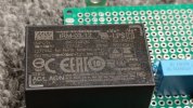
ideally going with a multi output isolated dc/dc converter using a 150w igbt chopper circuit would streamline everything. but thats for a later version.
to make use of the other side of the ht secondary tap. use one side to create lightly filtered b+ (main board plus 2nd board) and the other with its own rectifier to feed the overkill npn filter feeding b1 singal input tubes.
have three terminal block sections (ht 3-term, 6.3v 3-term, 5.0v 2-term) for a safe LZ (landing zone) and then two 1000v 2a rectifiers for the b+/b1 zones and a buck-boost regulator for the timer relay circuit using the 5.0v tap. a second pcb could contain b+ crcrc array and have its output terminal(s) physically closer to the out-txf b+ wire. the npn/darlington section could be on the main board with three terminals facing v1/v2 area. another strategically positioned pair of terminals would feed the heater wiring front end after going through a 0.2r high watage protection resistor.
heater offset would also be on the main board.
ideally going with a multi output isolated dc/dc converter using a 150w igbt chopper circuit would streamline everything. but thats for a later version.

sae-7125
Super Member
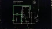
timer circuit sim was cleaned up plus changing the "optimal" seconds to reduce surge/over-voltage on startup
using 3.3uf with 3meg was not enough time so 4.7uf with 3meg is being tested for around 15-20 second delay. perhaps reducing the updated 68nf back down to 40nf across the relay contacts would help. maybe even 33nf for the b+ soft start.


sae-7125
Super Member
interesting test data and guitarist opinions about 6L6 and some variations.
sae-7125
Super Member

interesting notes to read through, especially the "Temperature coefficient and stability" section.
sae-7125
Super Member

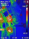
test the relay circuit power supply and seeing how low the b+ dropped after adjusting the bias core resistor

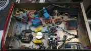
probably the last photo of the pentode configured output.
things have changed now that the circuit is back to ultra-linear txf taps. with the npn filter back in the system, no more 1uf caps for the v1/v2 rc nodes. need to adjust the trim resistors to calibrate current flow on v1/v2 triodes.
currently showing the 1.5uf x1 rated blue film cap on its side with 3 small narrow/rectangular 100nf in parallel to bump things up to 1.8uf. still need to adjust bias loading of the outputs and evaluate the resulting loaded b+. the extra z-shunt (chassis lower right) will be removed and the 1meg bleeder resistors are being revised. found a solution to the series cap trapped voltage during power off (relay 68nf in series with 1.5uf).

sae-7125
Super Member

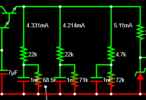
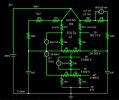
sim for the final mile design, also added v1/v2 sub-circuit loads for tuning the numbers after output bias is finalized (b+ will be lower soon).
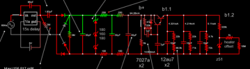
65nf across the front relay is/was 68nf advertised, it will be reduced to 33nf to improve soft-start protection when the relay clicks.
resistance for the heater offset load is approximated, need to do a baseline measurement across the 1k for accuracy.
the 120k npn base resistor could be bumped up to 150k or maybe 180k to reduce supply ripple to 50uv Rms or less (sim numbers). have to be careful how much the voltage drop across the darlington, too high will heat it up more than a little.
sim data attached, [edit] corrected wrong cap location on v1/v2 rc nodes (oops), caps after v-drop resistors.
shown above as 10nf each, didnt delete from sim.
Attachments
Last edited:
sae-7125
Super Member
measured the anode-anode impedance reaction with an LCR meter, when changing between 4/8/16r loads on each output tap. should have the numbers posted soon (100hz/1k/10k).

closer look at the factory rc filter nodes

and the expected voltages, when the preamp is connected. no idea how much the preamp connection might skew things vs solo amp(s).
since the soon-to-be calibrated b1 voltage is looking like 366v so far, i wonder if installing a 400v z-shunt after the npn filter and then feed each node with a 1k resistor to maintain some sort of isolation between each v1/v2 section (instead of 15k/22k/6.8k). adjusting the 2.2k lower for v2 cathode so closer to 6ma can be achieved, seems like dcg-designs went down to 1.5k if i remember correctly.
closer look at the factory rc filter nodes
and the expected voltages, when the preamp is connected. no idea how much the preamp connection might skew things vs solo amp(s).
since the soon-to-be calibrated b1 voltage is looking like 366v so far, i wonder if installing a 400v z-shunt after the npn filter and then feed each node with a 1k resistor to maintain some sort of isolation between each v1/v2 section (instead of 15k/22k/6.8k). adjusting the 2.2k lower for v2 cathode so closer to 6ma can be achieved, seems like dcg-designs went down to 1.5k if i remember correctly.