• The move to the new server is done. There are some software and database maintenance updates in process. This has us passing the hat around to help out. We appreciate any donations. Seriously, even a dollar helps. The payment page may be found here - https://www.audiokarma.org/support.html
in regards to bass-balance setting, has anyone noticed that the pot adjust affects Rg2 voltage drop? can adjust the balance pot to balance out the bass as described in the build manual or balance out each Vg1 voltage or balance out Vg2 on each bulb.

currently seeing 0.860v vs 1.03v at idle for Vg2 when control grids are balanced around 6.55v each.

 
Screenshot 2026-08-05 at 12-00-43 Untapped Potential Heath's W-5M Audiokarma Home Audio Stereo...png
www.audiokarma.org/forums/threads/untapped-potential-heaths-w-5m.1042474/post-16697476

so v1/v2 are getting stressed with the factory design surge, probably a good idea to revisit a b+/b1 z-shunt even though the timed relay circuit has reduced the potential for damage.

i am noticing a variation in power-off output thump when adjusting v1/v2 current draw and the initial npn filter tests (when feeding b+ and b1, thump was zero). after removing the output bypass caps there was still a significant thump.
 
www.audiokarma.org/forums/threads/untapped-potential-heaths-w-5m.1042474/post-16697490
*16309 design limitations

and now the LCR chart mentioned earlier:

[output-tap/load] 100hz/1k/10k

[4 / 4.16] 11k / 11.37k / 11.18k
[4 / 8.21] 18.5k / 18.7k / 18.7k
[4 / 16.39] 31.9k / 36k / 32.4k

[8 / 4.16] 5.15k / 5.27k / 5.36k
[8 / 8.21] 8.58k / 9.1k / 8.94k
[8 / 16.39] 15.5k / 16.4k / 15.8k

[16 / 4.16] 3.36k / 3.4k / 3.47k
[16 / 8.21] 5.36k / 5.51k / 5.57k
[16 / 16.39] 9.06k / 9.7k / 9.6k

using a pair of 100w 8r load resistors in series/parallel/solo configuration, amp circuit had all the tubes installed and could be powered up for normal operation (minus the LCR meter connection).

no idea if the out-txf on one of both amps have been electrically damaged over the years or are showing signs of abuse from the factory circuit.
 
n regards to bass-balance setting, has anyone noticed that the pot adjust affects Rg2 voltage drop? can adjust the balance pot to balance out the bass as described in the build manual or balance out each Vg1 voltage or balance out Vg2 on each bulb.

currently seeing 0.860v vs 1.03v at idle for Vg2 when control grids are balanced around 6.55v each.
thats your tubes being unmatched. You want to adjust that for equal current through the tube. The grid voltage doesn't matter, but the better the tube match, the closer those will be.
 
Screenshot 2026-08-06 at 11-26-18 Untapped Potential Heath's W-5M Audiokarma Home Audio Stereo...png
www.audiokarma.org/forums/threads/untapped-potential-heaths-w-5m.1042474/post-16697508

Screenshot 2026-08-06 at 11-30-46 Untapped Potential Heath's W-5M Audiokarma Home Audio Stereo...png
www.audiokarma.org/forums/threads/untapped-potential-heaths-w-5m.1042474/post-16697535

i might go with 470nf up front instead of 100nf and 220nf for the output stage vs 1000nf stock. to evaluate power-off thump reaction. v2 cathode resistor is at 2k (5.35ma) right now but it will be revised down to 1.8k even though 1.7k might be ideal.

the dcg mod obviously removed the bypass cap so it will be interesting to hear how the normal cathode bias with cap reacts.
 
in regards to bass-balance setting, has anyone noticed that the pot adjust affects Rg2 voltage drop? can adjust the balance pot to balance out the bass as described in the build manual or balance out each Vg1 voltage or balance out Vg2 on each bulb.

currently seeing 0.860v vs 1.03v at idle for Vg2 when control grids are balanced around 6.55v each.
The intention of the bass-bal control, is to make a fine adjustment to the Vg1 voltage, so that the DC current through each half of output transformer balances, to avoid core saturation. The only way to set it is as per the manual.

The V shaped graph in the manual shows how core saturation causes distortion at low frequencies. I think the W5M had to include this control, because the Peerless output transformer has a fairly small core, and is sensitive to saturation.

With my amplifiers, one set of KT66s is slightly better matched than the other, so changing tubes needs a tweak of the control.

The only way to have all voltages equal is perfectly matched tubes, but if they aren't, equal current through the tx is by far the most important thing to achieve by use of this control.
 
Screenshot 2026-08-06 at 11-42-55 Untapped Potential Heath's W-5M Audiokarma Home Audio Stereo...png
www.audiokarma.org/forums/threads/untapped-potential-heaths-w-5m.1042474/post-16697548

interesting to note the importance of the 6L6 class of tubes. with this boondoggle project and targeting around 15w output that would make 5881/7581a and other glassware a possibility for rolling options. a pair of full metal jacket 6L6's would be interesting.

is it a bad thing to have more tube rolling options with an amp circuit, that doesnt stress/bork the bottles with every on/off cycle?
 
equal current through the tx is by far the most important thing to achieve by use of this control.
definitely something to focus on.

looks like dave's design has the following numbers (anode/cathode):
v1.1 : 75v/1.62v = 3.44ma
v1.2 : 240v/80v = 3.63ma
v2 : 245v/10v = 6.67ma = 3.33ma each triode

although the different output circuit bias/loading might benefit the most from the calculated currents above.
 
If its running under 6L6 sort of operating conditions, any of the higher-rated variants will work fine and not be stressed at all. Its all within the same family so its not really anything odd. The amps that allow use of extremely different tubes has always made me wonder what its really tuned for.

Swapping tubes doesn't really stress them physically so long as its done carefully. Don't pull them out by the bottle, don't pull them when hot enough to remove fingerprints so you end up flinging them across the room, etc. The more you use the sockets the more it wears those out of course.
 
the circuit is ever evolving though trial/error/what-if/oops with some recent snapshots along the way.

heathkit w5m - 103.jpg
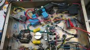
slowly adjusting step-down caps, bias core resistance (factory 330r 7w) and the v1/v2 feed nodes from the npn filter (output = b1). bypass caps, using 105c generic recap bin 100uf 63v just for testing.

heathkit w5m - 104.jpg
step-down caps closer to a final value (2101nf measured, 1.5uf+470nf+100nf).

front end z-shunt lowered from 500v to 480v (160v x3) also 200+200 added to b+ for excessive over-voltage safety.

v1--v2 coupling caps changed to 470nf and v2--outputs changed to 220nf.

bias core reduced from 330r//3k to 250r solo.

v1/v2 b1 feed resistors changed from previous 5.6k/5.6k/1.5k to 22k/22k/1.5k (factory 15k/22k/6.8k plus caps).
 
interesting to note dmm probe noise injection disrupting the circuit when probing v1 front end of lower (red cap closest to outside of chassis) film capacitor. which sheds some light on the importance of the 15k/20uf rc b1 filter node. further testing of dmm probe and music has shown a cap is definitely needed on v1. a 3.3uf 450v film revealed much, other two nodes no cap installed initially.

so... not just a b1 supply filter node, there is some magic hiding in the capacitance of the node (smooth/stable bass amplitude extension vs volume control position).

**next batch of photos will show the plot twist better, it ended up being a double in more ways than expected.

bypass caps updated to 10k hours 120uf 100v low esr, output flavor changed during sonic testing.
 
i wonder what the "ideal" cap value for each node would be, assuming all three need a cap of some sort.

the factory 20u/20u/20u seems quick/easy/generic/convenient although most likely effective. another possible compromise for this attempt at a full-film renovation would be adding one of the extra 22uf 450v 10k hours caps from the get-set-go 300b project posted in season-2. the other 450v option would be around 120uf which seems a bit much for the v1.1 position and the others.
 
heathkit w5m - 105.jpg
attempting to view component alignment with bottom panel vents, cold air source vs bypass cap location.

heathkit w5m - 106.jpg
the other vent, chassis mount b+ filter resistors.
 
heathkit w5m - 107.jpg
finally making progress with the oddball renovation project, amp now glass side up.

basic, fully enclosed circuit testing plus need to revisit power-off pulse reduction ideas.
 
when reducing the v1.1 and v1.2 triode current settings (via b1 feeder resistors) the pulse became more pronounced/worse even though swapping the 100nf and 1000nf factory positions (now 470nf and 220nf) helped change the pop frequency (more midrange less bass, woofer pull-in excursion amplitude & decay).

no idea if running 1.1 or 1.2 or both around 5ma is normal for 12au7. especially since the factory design (even though dave debunked schematic numbers) is 4.68/4.54ma which isnt too far from 5.0ma idle. perhaps the mixture of one triode pulling the circuit down during power-off and finding a suitable b1 rc node capacitance might balance things out, or make it worse...

the general idea being, using a front end triode to drain/sink/slurp the stored energy in the area (at power-off) to reduce electron belch/burp potential... especially out the outputs (lower electron tract) and into the speakers which would inconvenience the entire room (silent butt deadly meets sonic no medley). chassis might need a change of paint afterward.

further "what if" testing needed.
 
Screenshot 2026-08-09 at 00-54-22 7027a bias sim 002.txt - Circuit Simulator.png
updated the bias sim with the current bench test numbers

with the bass-balance adjusted noticeably to one side of the pot, should have measured the pot position since some of the numbers dont line up exactly.

data attached.

-28.4v cat/g1

cat/24r/250r/68r/150r/b-
36.2v/35.0v/10.6v/7.2v (inside bulb)

anode/cathode = 325v (inside position bulb)
250r (bias core) = 24.5v = 98ma = 49ma each output
325 * 0.049 = 15.925w

at 120v mains 82w idle and 2101nf step-down capacitance. or perhaps the txf caps should be seen as a limiter since the step-down doesnt occur until full load is warmed up.
 

Attachments

Screenshot 2026-08-09 at 01-00-04 7027a - main circuit 003 test.txt - Circuit Simulator.png
updated the b+ schematic as well, dialed in the v1/v2 numbers even though an upcoming adjustment is pending (pop reduction).

the pair of z-shunts should help protect the b+ glassware+caps from any over-voltage power-on situations. i wonder if it will interfere with the normal b+ sinewave offset that the outputs will create vs normal cap filter taking the hit.

the 1r between b+ and b1 is for sim experiments only, not used in the bench circuit. not sure why i put 2102nf up front vs 2101nf measured, typo.

data attached.
 

Attachments

heathkit w5m - 108.jpg
comparison with amp 2 of 2, things did not go as planned. plot twist 2 of 2 inbound...

heathkit w5m - 109.jpg
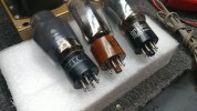
the delco bulb looks like its seen better days, guessing this is the mismatched floater amp that was acquired at some other point in time. the 12au7's up front had no silkscreen and unusually clean glass. either way the amp will be receiving new tubes so no big deal.
 
Back
Top Bottom