• Please note that Audiokarma will be offline briefly for updates early on Monday morning, September 28th.
The caps to ground aren't just filtering, they are decoupling at each stage to isolate it from the other amplifier stages. Ideally you want a low impedance to ground at well below 20hz so B+ is also at AC ground. Without that the load the tube works into varies by frequency, and it can have unwanted coupling to the adjacent stages which causes low frequency stability problems.

Z of a 20uF at 20hz is about 400 ohms, a 3.3uF is about 2.4K.

I wouldn't judge those tubes just on their visual merit. That grey coating inside was done on purpose, its a sort of shielding. If they test well, fair guess they are at least as good as anything you can buy new.
 
Ideally you want a low impedance to ground at well below 20hz so B+ is also at AC ground.
would balancing the 470r cathode resistor with an 11.2uf anode cap (30hz design target) be of any value/significance or is a high capacitance for low as possible xc on the anode a better design? balancing the [triode+47k] with -470r and +470r for some type of signal symmetry.

finding a 33u or 47u at 450v (electrolytic) would not be difficult, perhaps the 120uf 450v staring at me from the 300b parts shelf isnt too over the top as initially thought.

b+ at ac ground, that would suggest a sonic benefit if adding another 30uf b+ filter cap (30//30 = 60uf). low resistance for ac signal would be noticeable on high frequencies above 10khz (treble, detail, recording acoustics, instrument placement).
 
also, should the first triode operate closer to the dc and ac load line intersection?

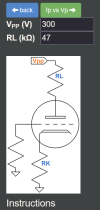
Screenshot 2026-08-10 at 16-13-11 12AU7 Calculator.png

Screenshot 2026-08-10 at 16-21-54 12AU7 Plate Characteristics.png
still need to experiment with power-off pop reduction. it can be done, just needs the correct ingredients.
 
would balancing the 470r cathode resistor with an 11.2uf anode cap (30hz design target) be of any value/significance or is a high capacitance for low as possible xc on the anode a better design? balancing the [triode+47k] with -470r and +470r for some type of signal symmetry.
the cathode and anode don't work independently. A small cap plate and cathode is effectively those two caps in series so far as the tube "sees" it.

b+ at ac ground, that would suggest a sonic benefit if adding another 30uf b+ filter cap (30//30 = 60uf). low resistance for ac signal would be noticeable on high frequencies above 10khz (treble, detail, recording acoustics, instrument placement).
makes a lot less difference at high frequencies honestly, ESR starts to become more of a factor at some point. Z of a 30uF cap at 15khz is 0.35 ohms. Doubling the cap cuts it in half, but at less than 1 ohm thats not going to really matter. Two 15uF in parallel will probably do more for you just for the lower ESR that it should produce.

don't know on the operating point thing, ideally it should be biased wherever it produces the least distortion but with a direct coupled setup you also have to bias it where the inverter works properly so its a bit of a balancing act.
 
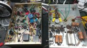
heathkit w5m - 110.jpg
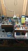
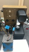
comparing modified vs unmodified w-5m amps. staring to install the rebuilt mains-txf in the second amp.

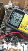
heathkit w5m - 111.jpg
electrically inspecting an important component before sinking lots of time into the second half of the amp renovation project.

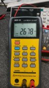
i wonder if 1.6 meg-ohm is normal when measuring from center-tap out-txf to v3 (outside bulb) anode/plate. something tells me no its not.
 
Definitely not. Couple hundred ohms at the high end would be typical, but for higher power tubes closer to 100 is more normal.
 
That does not look even close to right.

Just as a thought experiment consider the voltage loss. Idle for this is probably in the neighborhood of 50mA per tube. Over 3.3K thats 165 volts. Typical loss in an output transformer usually barely breaks into double digits.
 
heathkit w5m - 116.jpg
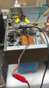
v3 screen grid to ct

heathkit w5m - 117.jpg
2678r

i wonder if this is how the power on/off self damage plays out with the stock amp circuit. seems like dave's write up or somewhere talked about one of the outputs gets hit on a regular basis not both.
 
heathkit w5m - 120.jpg
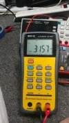
v4 screen grid to ct

heathkit w5m - 121.jpg
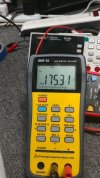
175.3r

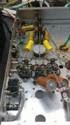
so half of the out-txf is ok and the other half has been stressed or something. no idea if there is any history of operator error, bad tube or wrong tube or whatever. hook up wire inside the chassis seems rather thin in regards to insulation thickness vs high voltage. thin walled wire flat to the metal chassis might be problematic, arcing potential.
 
175 ohms looks more like what I'd expect, 315 ohms seems high, but a mismatch side to side isn't unusual. Not typically that much different though. May want to see if anyone else has DCR numbers for these to see how it compares to your readings.
 
Try applying an AC voltage like 6.3V between the 8 ohm and common terminals on the secondary of the transformer, and see if it appears on the primary at the proper ratio. Fingers crossed this is measurement error and not a failed tx.
 
heathkit w5m - 122.jpg
extracting the out-txf

heathkit w5m - 123.jpg
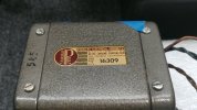
confirming the part number before the patient gets checked-in for surgery, document any allergies.
 
heathkit w5m - 124.jpg
extraction not too difficult although installing the next one will take some time.

no idea if another 16309 will be sourced from a local hoarder, they dont like parting with their parts until after the wife liquidates the toy collection during the funeral.

finding another amp with a verified healthy 16309 would be another option even if it has a burned up mains-txf since most of those will be on borrowed time by now.
 
heathkit w5m - 125.jpg
opening up the wires side, high voltage rated paper/material

heathkit w5m - 126.jpg
lots of vintage tar and the txf core is noticeably off-center vs inside spacing
 
Back
Top Bottom