You are using an out of date browser. It may not display this or other websites correctly.
You should upgrade or use an alternative browser.
You should upgrade or use an alternative browser.
heathkit w-5m renovations [boondoggle edition] quantum vacuum deep dive
- Thread starter sae-7125
- Start date



sae-7125
Super Member
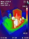
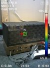
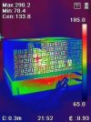
with the top down, lots of hot spot reflections
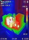
some thermal info about the mains-txf although too much reflection from v1/v2
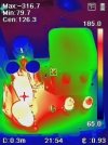
outputs too close to everything else, not such a good idea and yet a vintage norm...
not sure about the rectifier in the back, its starting to warm up to slightly above room temp (oh the horror). at least the disconnected factory multi-caps are not getting cooked to death on 2 sides, just one. all senseless snarking aside, its interesting to see the modified thermal footprint on the tube deck. since there are a few chassis mount resistors in action that dont normally exist.
sae-7125
Super Member
some type of tube cage would be a good idea either for both pairs of fire together or one cage per pair like a salt & pepper shaker carrier.

something made of 1950's sourced materials plus a stylish handle. obviously tall mesh walls for full effect/protection. maybe retain the pattern of the original full cage/cover, just random ideas...
something made of 1950's sourced materials plus a stylish handle. obviously tall mesh walls for full effect/protection. maybe retain the pattern of the original full cage/cover, just random ideas...

I've never seen a tube amp with that sort of cover arrangement. It was all or nothing, with the idea of hiding and keeping everything far away from the bits inside. Would be interesting to see what it looks like after an hour with the cover on vs cover off to see how much extra heat it actually retains. It may not be enough difference to really matter.
but generally I agree that thermal management on most old amps is not ideal, though everything ran hot back then so maybe it was just considered less of a problem. Those caps often lasted decades despite being placed where they cooked constantly.
but generally I agree that thermal management on most old amps is not ideal, though everything ran hot back then so maybe it was just considered less of a problem. Those caps often lasted decades despite being placed where they cooked constantly.
sae-7125
Super Member
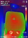
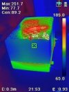
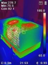
closer look at the mains-txf, v1/v2 hot spot reflections
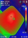
top is noticeably hot, not surprising with around 80w of heating potential
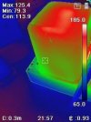
base is a little cooler, used a chunk of cardboard to block out any reflections
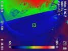
0.3 meters = 11.8 inches, camera distance is probably closer than that (temps slightly higher vs actual). emissivity of 0.93 vs txf shell surface shouldnt be too far off. room temp is probably near 73f.
sae-7125
Super Member
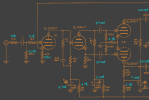
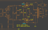
page-1, not perfect but it doesnt need to be. re-re-adjusted a few things and settled on the above values. an establish reference point to compare future modz with.
interesting to note, when bumping up the cap feeding v1 pins 1 & 7 it also translates to more power-off pop potential (sabotaging front end loading). adjusting v1 pin 3 cathode resistor higher helps to compensate, also allows for higher input volume before distortion starts to limit performance/quality. overall low frequency stability has improved vs the initial 1u/1u/1u and deleting the three little caps (multi cap) completely.
it would be interesting to add a 330k 1w in parallel with the now 4.7uf cap to possibly eliminate power-off pop / woofer (-)excursion without dialing up the current through v1.1 beyond 5.2ma (into reduced lifespan territory, possibly).
should consult 12au7 data sheet and most of its variations for a distortion-vs chart to figure out ideal current per triode.

sae-7125
Super Member
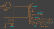
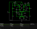
page-3, cleaned up the front end circuit
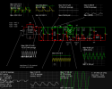
page-4, the sim schematic could be trimmed down to the bare minimum and delete some of the testing variances, like the switch in series with the output tube load equivalent resistor (and 1r, 10meg, 1gig).
the bias sim (previous posts) helps to estimate how much the outputs will load down the system. timer circuit was documented in an earlier post as well.
sae-7125
Super Member
www.youtube.com/watch?v=BmPxB2Xekf8
*interesting vid about 12au7 and falstad sim
*interesting vid about 12au7 and falstad sim
sae-7125
Super Member
www.youtube.com/watch?v=vweUnrfko3Q
*triode biasing: design and analysis
*triode biasing: design and analysis
sae-7125
Super Member
www.youtube.com/watch?v=3F1UYLsOXGo
*topic 63, more focus on 12au7 calcs and curves
*topic 63, more focus on 12au7 calcs and curves
sae-7125
Super Member
| TUBE | MU | EX | KG1 | KG2 | KP | KVB | CCG | CPG | CCP | RGI |
|---|---|---|---|---|---|---|---|---|---|---|
| 6DJ8 | 28 | 1.3 | 330 | 320 | 300 | 2.3P | 2.1P | 0.7P | 2k | |
| 6L6CG | 8.7 | 1.35 | 1460 | 4500 | 48 | 12 | 14P | 0.85P | 12P | 1k |
| 12AX7 | 100 | 1.4 | 1060 | 600 | 300 | 2.3P | 2.4P | 0.9P | 2k | |
| 12AU7 | 21.5 | 1.3 | 1180 | 84 | 300 | 2.3P | 2.2P | 1.0P | 2k | |
| 6550 | 7.9 | 1.35 | 890 | 4800 | 60 | 24 | 14P | 0.85P | 12P | 1k |
| KT88 | 8.8 | 1.35 | 730 | 4200 | 32 | 16 | 14P | 0.85P | 12P | 1k |

Improved vacuum tube models for SPICE
Improved vacuum tube models for SPICE simulations Table of ContentsPart 1Equations for vacuum tubes New equations SPICE Parameters Finding parameters by trial-and-error Plate curves Output transformers Example: original PAS preamplifier LessonsPart
www.i-t.com
useful mu and kg1 numbers for falstad sim and its triode settings.
sae-7125
Super Member
since there seems to be an issue uploading files/photos right now, confirmed with "the" moderator on duty, will need to do some typing.
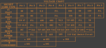
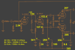
looking at the voltage drop across v1.2 a couple posts ago, things seem unusually low (build manual indicated 180v) and in need of a rebalance. page-2 voltages are ready and waiting to be posted.
looking at the voltage drop across v1.2 a couple posts ago, things seem unusually low (build manual indicated 180v) and in need of a rebalance. page-2 voltages are ready and waiting to be posted.