

You are using an out of date browser. It may not display this or other websites correctly.
You should upgrade or use an alternative browser.
You should upgrade or use an alternative browser.
heathkit w-5m renovations [boondoggle edition] quantum vacuum deep dive
- Thread starter sae-7125
- Start date


sae-7125
Super Member
Help understanding cathode bypass capacitor
I have been studying various amplifier schematics over the past few weeks, and I have been reading a lot of threads, but I can't find a precise answer about what effect a cathode bypass resistor has on the sound quality of a hi-fi audio power amplifier. One old thread turned into a multi-page...
RC Circuit Calculator | Time Constant, Charging, Filters
Analyze RC transient behavior and filter response with this comprehensive calculator.
sae-7125
Super Member
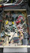
and now the final mile/km wiring slog to try and bring things together for more sonic testing plus basic health measurements.
in the photo above there is an important wire missing. didnt realize it until the initial 120v test run without timer relay active, the b+ was limited to 40nf series feed cap (good thing too). also good that the z-shunt was in attendance, no kaboom detected. output tubes (7027a x2) were installed during initial power up test, if not the oops voltage would have wandered higher than 500v (at z-shunt).
timer circuit pre-tested for timing accuracy, external 12v supply used. small modular pcb mount supply inbound.

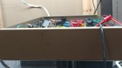
side profile of the mess that would make a picasso look perfectly symmetric
the front end card is mounted to one of the tube rectifier bolts (shared tether point) and seems solid. the testing step-down feeder caps are waiting for final upgrade and dialing in the b+ to optimal voltage. chassis mount 250r with mica's are waiting for inbound 300r changeover.
sae-7125
Super Member
updated schematics would be a good idea to post soon.
the g2 z-reg circuit is connect to the same point as b+ and not after the b1 1.5k/7uf filter node. still need to adjust g2 47k feed down to something that doesnt allow the screen grids to brown out at high volume (22k-33k range maybe). should keep an eye on 130+130v 5w zener temp when adjusting.
still using 1uf for the v1/v2 b1 rc filter nodes. might bump up to 4.7uf for comparison testing. having the npn filter circuit feed b1 nodes would probably be optimal since 100uv or less of noise would be beneficial (not installed yet). not to mention b1 sub-circuits pull far less milli-amps, less transistor stress and could bump up filter control resistors for 10uv noise performance.
full wave bridge rectifier shown is the initial 2a rated small module. didnt heat up as bad as expected, might be a permanent resident (undecided thus far).
triple 100k 3w will be changed to 33k 5w even though temp will rise more than a little, 9w = around 150f/65c.
the g2 z-reg circuit is connect to the same point as b+ and not after the b1 1.5k/7uf filter node. still need to adjust g2 47k feed down to something that doesnt allow the screen grids to brown out at high volume (22k-33k range maybe). should keep an eye on 130+130v 5w zener temp when adjusting.
still using 1uf for the v1/v2 b1 rc filter nodes. might bump up to 4.7uf for comparison testing. having the npn filter circuit feed b1 nodes would probably be optimal since 100uv or less of noise would be beneficial (not installed yet). not to mention b1 sub-circuits pull far less milli-amps, less transistor stress and could bump up filter control resistors for 10uv noise performance.
full wave bridge rectifier shown is the initial 2a rated small module. didnt heat up as bad as expected, might be a permanent resident (undecided thus far).
triple 100k 3w will be changed to 33k 5w even though temp will rise more than a little, 9w = around 150f/65c.

maxhifi
Addicted Member
Have you seen this?results from a quick "contact us" interaction with hammond txf earlier today:
View attachment 3805902
.
View attachment 3805901
.
View attachment 3805903
bulk of my question to them.
their answer was quite brief and perhaps raises more questions... maybe i should have tried to send them a small screenshot of the mains txf on the schematic.
sae-7125
Super Member
looks like some delicious design parameter info.
full wave choke input load calculation: v(peak) dc = 45% of v(2nd, Rms).
interesting to see (910 * 0.45 = 409.5v dc) even though the math still doesnt line up with the excessive voltages being measured. perhaps the difference between slightly loaded vs max loaded or something? but even that doesnt make much sense either when looking at the mains txf voltages written down (posted earlier) showing completely unloaded measurements.
115v mains equaled 933v Rms full secondary which isnt too far off from the 455+455 on the schematic.
comparing to full wave bridge capacitor input load, will be interesting.
140ma * 1.54 (fw choke) = 215.6ma
910v * 0.45 (peak & avg) = 409.5v
= = 88.2882w
vs
140ma * 0.62 (bridge cap) = 86.8ma
910 * 1.41 (peak) = 1283.1v
910 * 0.90 (avg) = 819v
= = 111.373w
= = 71.0892w
more data points to crunch either way. nice find @maxhifi well done sir.
full wave choke input load calculation: v(peak) dc = 45% of v(2nd, Rms).
interesting to see (910 * 0.45 = 409.5v dc) even though the math still doesnt line up with the excessive voltages being measured. perhaps the difference between slightly loaded vs max loaded or something? but even that doesnt make much sense either when looking at the mains txf voltages written down (posted earlier) showing completely unloaded measurements.
115v mains equaled 933v Rms full secondary which isnt too far off from the 455+455 on the schematic.
comparing to full wave bridge capacitor input load, will be interesting.
140ma * 1.54 (fw choke) = 215.6ma
910v * 0.45 (peak & avg) = 409.5v
= = 88.2882w
vs
140ma * 0.62 (bridge cap) = 86.8ma
910 * 1.41 (peak) = 1283.1v
910 * 0.90 (avg) = 819v
= = 111.373w
= = 71.0892w
more data points to crunch either way. nice find @maxhifi well done sir.
sae-7125
Super Member
apparently troubleshooting ak issue has been in full swing for a while:
www.audiokarma.org/forums/threads/cant-post-cant-edit-permissions-etc-please-use-this-thread.733688/page-67#post-18421045
the new server should be interesting, wonder if it has more cup holders and a refreshed hood ornament.
www.audiokarma.org/forums/threads/cant-post-cant-edit-permissions-etc-please-use-this-thread.733688/page-67#post-18421045
the new server should be interesting, wonder if it has more cup holders and a refreshed hood ornament.
maxhifi
Addicted Member
The W5M uses a full wave capacitor input, per the Hammond drawing, followed by a choke filter. Not a choke input.
The voltages they show are fully loaded and with a arbitrary sized capacitor. Still, it shows a good basis of comparing how to select a transformer current rating. The main point I am trying to get across is that the bridge using half the winding will put more stress on that winding than it is designed for.
A choke input is a whole other beast. Probably the best sort of power supply, but don't be tempted because the existing choke in the W5M is unsuitable for use as a choke input filter since the peak ripple it would have to handle is too high.
The voltages they show are fully loaded and with a arbitrary sized capacitor. Still, it shows a good basis of comparing how to select a transformer current rating. The main point I am trying to get across is that the bridge using half the winding will put more stress on that winding than it is designed for.
A choke input is a whole other beast. Probably the best sort of power supply, but don't be tempted because the existing choke in the W5M is unsuitable for use as a choke input filter since the peak ripple it would have to handle is too high.
maxhifi
Addicted Member
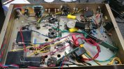
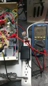
actually, scratch that 66r assumption. not dealing with a full sinewave since its been rectified...
The issue is the peak to peak ripple voltage across the choke. In a choke input filter it gets really high, compared to in a CLC filter. A choke input filter requires a specially designed choke. Ripple frequency is 120Hz.



sae-7125
Super Member
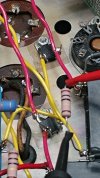
the 250r 35w with mica's are a temporary testing solution, mica helping to reduce corona potential between the resistor legs and chassis ground. metal mounting hardware on the metal (isolated) component package tab is not an immediate concern. the replacement 300r 35w is fully enclosed even though it will still need a mica for the legs.
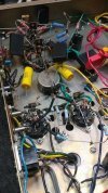
still a scattered mess on this side of the chassis. z-reg 130+130v feeding g2 (470r g2 each output) will be relocated and component leg length will be trimmed for final fitting. triple 100k 3w will be swapped out for 33k 5w single. the g1 10k's will be bumped up to 33k to evaluate signal restriction performance (volume throttle).
should have some thermals available soon to see where all the hot spots are and how bad.



sae-7125
Super Member
i wonder if bumping up the 47k to 120k would be a better alternative. since i am targeting 15-18w output that should eliminate the "below 30hz" trouble that the original/1st-gen out-txf is sensitive to.
might consider 220uf bypass caps to improve subsonic performance although that could be going a little too far.
might consider 220uf bypass caps to improve subsonic performance although that could be going a little too far.