• The move to the new server is done. There are some software and database maintenance updates in process. This has us passing the hat around to help out. We appreciate any donations. Seriously, even a dollar helps. The payment page may be found here - https://www.audiokarma.org/support.html

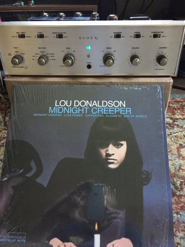
HH SCOTT 233 rebuild

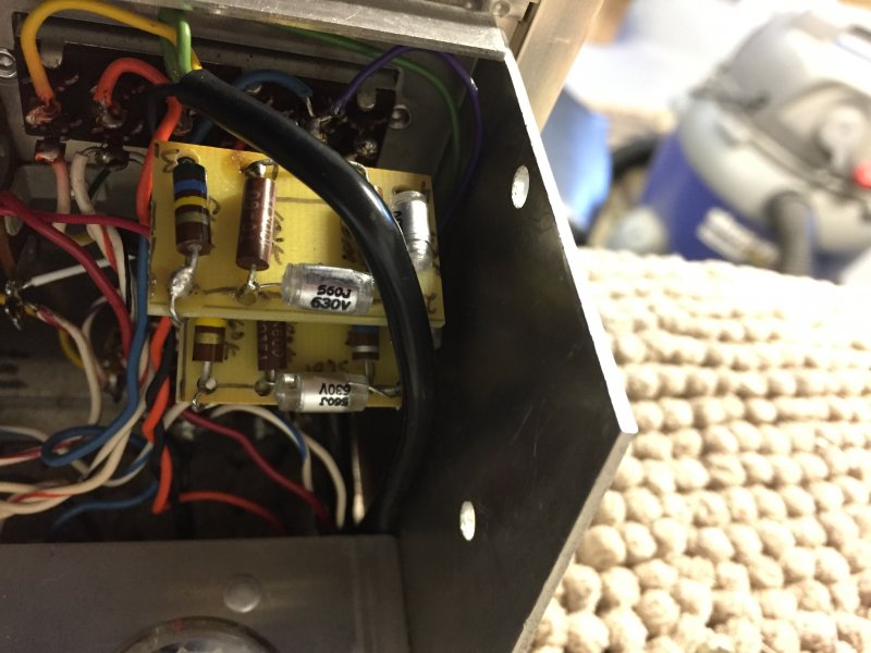
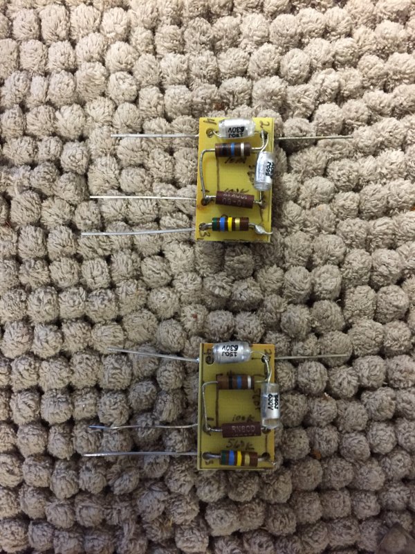
I rebuilt the Phono EQ PEC chips with discrete parts . Used Polystyrene caps. It really sounds much sweeter and more detailed, It is now on par with the Line stage.

 
I believe I am pretty much done with Updating and modifying The HH Scott 233. I did changed the grid load resistors on the line stage to 47k instead of the 27k I had in there. Mostly I had the volume at 12 oclock or higher before. now its just a bit lower like 10-11 oclock.
 
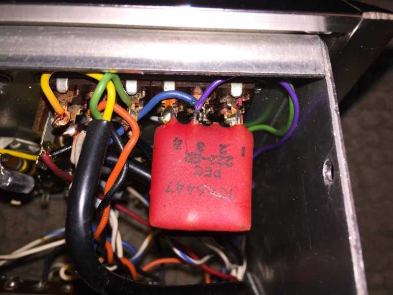
I can tell you 100% the 222er is the Riaa equalization of the phono stage. you dont want to bypass it if you are using the phono for vinyl playback. You can bypass the 299 PEC in the line stage, but you will have too much gain and need to reduce it, via voltage divider etc. certainly do one at a time and listen. I left all of the carbon comp resistors and the noise level is perfectly acceptable. I did recently replace the 3.3 ohm bias measuring resistor as it would drift with the heat too much. I installed 4 individual precision 1 ohm Metal Film resistors, most people use 10 ohm as they are easier to measure by digital VOM.

I do feel the phono stage improved by replacing the PEC 222er.
 
A channel Imbalance can be caused by faulty pecs. I had one fail and cause one channel to have more gain due to losing the feedback around it. I spent way too much time lookin at the working channel (the quieter one) before I located the actual problem. The problem was in the feedback loop so the louder of the 2 was actually the problem channel. I had replaced all the resistors and caps in the phonostage twice at that point... The pec in these is used to Taylor the RIAA curve by applying local feedback around the stage. This accomplishes 2 things. Reduces gain, and sets the correct frequency response for the stage. I was unable to repair my PEC, and I ended up building replacements on a peice of perf board and soldering it in where the old ones were. Unfortunately you are going to need an oscilloscope to diagnose this correctly, and even then you need to have your head about you, because there is 500 in there and lots of things to check out.
 
I agree about the PEC chips. I would replace both . They could be the cause of the channel imbalance . Unless it is also occurring on line level inputs , then not.

Lots of very high end Japanese hifi uses carbon comp resistors . Usually hand selected and higher wattage though. I have also seen my fair share of off value cheap metal film too.
If I use metal film I only use military grade stuff , lots of cheap metal film resistors are made poorly and even use steel ends and leads. Get a magnet and check. Dale, irc, prp are great though.
 
All but one of the white ceracaps in mine measured good. They sound muddy and blurry though, relative to the
Vitamin q etc. The vitamin Q are really wonderful though , liquid , full, even , very nice highs , silky with clarity .
 
The thermal drift was why I did away with the 3.3 ohm bias measurement resistor. When trying to calculate the mv’s the value would keep changing higher . When your talking 1 ohm or 2 or 3 it makes a difference in the calc. But doubt it really affects anything else.

I am contemplating a se 300b build and would be interested in your experiences with them. I recently found a set of altec model 19’s and my cj premier 11a is barely cracked open . Sounds good though. The guy I got them from was running some custom built SE Amps and it was a bit magical sounding .
 
The 4 section 75/75 can is positive grounded as it is part of the bias supply . As I recall all others are negative grounded.
 
I'm also a very new student to bias supply for the center tap. Slowly understanding push pull tube amps. But, to be sure, if I use individual caps as I'm doing, positive is positive and negative negative no matter what right? Again forgive the confusion. Do you agree where I drew in the polarities I'm correct? I hate blowing up good capacitors let alone cherry vintage amps

No, I do not agree with two of the circled drawings. You have them reversed. Only the quad can 75uf 75v
Is positive ground , it is part of the negative bias supply and includes v102,v2, v101, v1 preamp tube filaments . All other power supply capacitors are negative ground .

I might suggest you do not replace the quad can cap 75/75 until you have replaced the other can caps and power up on a dim bulb tester or I use a variac and ammeter . To make certain you have no shorts . A polarized cap can survive reversed polarity , maybe, it might also fail . It will not work well though. The bias caps are working at much lower voltages and do not fail at the same rates as the higher voltage caps do. It’s usually the first cap in the power supply that fails or leaks due to the very high ripple it sees .
 
No, I do not agree with two of the circled drawings. You have them reversed. Only the quad can 75uf 75v
Is positive ground , it is part of the negative bias supply and includes v102,v2, v101, v1 preamp tube filaments . All other power supply capacitors are negative ground .

I might suggest you do not replace the quad can cap 75/75 until you have replaced the other can caps and power up on a dim bulb tester or I use a variac and ammeter . To make certain you have no shorts . A polarized cap can survive reversed polarity , maybe, it might also fail . It will not work well though. The bias caps are working at much lower voltages and do not fail at the same rates as the higher voltage caps do. It’s usually the first cap in the power supply that fails or leaks due to the very high ripple it sees .
I'm in the process of rebuilding a 233 amp and am needing advice on the 3 can cap replacements. I see your rebuild uses CE Mfg 40/20/20/20 525V and CE Mfg 20/20/20/20 475V. My question for you if you don't mind; what did you do with the two 25uf 25V sections on the can cap that is 20uf X4? And how did you deal with the the bias supply can cap with 100uf X4? Thanks very much for you help. I'm putting together an order for recapping this 233.
 
I probably used the 20uf section for the cathode bypass. We are talking about the difference in frequency response of a few hertz below 10-15 hz.
 
Another option is to use an individual 22µFD @ 35VDC (50 VDC etc.) at the tube instead of using the section of the filter capacitor.
 
Back
Top Bottom