• Please note that Audiokarma will be offline briefly for updates early on Monday morning, September 28th.

HH Scott Owners Thread

I posted a thread a few weeks back about my 340B but no one replied. If anyone has a working restored 340B, and have a signal generator, scope and a 8 ohm 100watt dummy load, can you measure the power you get out of your amp using the 0 speaker connection for the (neg) and 8 ohms for the positive? Mine produces 10v peak to peak before clipping which only works out to 1 watt RMS or so. Something doesn't make sense as I am able to hook to up to speakers and it's quite loud. I am thinking it has to do with the 4 ohm tap being grounded on these amps and a lot of the Scott's where a lot of amps ground the black tap lead.

Could you show how you calculate 1 watt RMS from your measurements? If the output actually swings from +10v to -10v across your 8 Ohm load I caluculate a little over 6.25 watts RMS. Still sounds too low though. I don’t see how the grounding of the 4 Ohm tap would cause this issue.
 
Could you show how you calculate 1 watt RMS from your measurements? If the output actually swings from +10v to -10v across your 8 Ohm load I caluculate a little over 6.25 watts RMS. Still sounds too low though. I don’t see how the grounding of the 4 Ohm tap would cause this issue.
10v pp across 8 ohms =about 1 watt rms. 10vpp/2.83=3.53 3.53x3.53 /8 ohm load=1.56 wrms. Yes it does seem low all the 6u8 stages are ok feeding each 7591 tube..voltages are ok on the plates and tubes biased to .33ma each.
 
10v pp across 8 ohms =about 1 watt rms. 10vpp/2.83=3.53 3.53x3.53 /8 ohm load=1.56 wrms. Yes it does seem low all the 6u8 stages are ok feeding each 7591 tube..voltages are ok on the plates and tubes biased to .33ma each.

I thought Vrms = .707 * Vpeak
Prms = Vrms*Irms or =(Vrms)^2/R

So, Prms = (10*.707)^2/8 = 6.25 watts. Perhaps I misunderstand how you measured 10Vp-p.
 
Hello. I own several sets HH Scott loudspeakers: S-17, S-42, S176 and S177. I like them a lot. They sound very good with my old vintage receivers.:)

EDIT: Oops, this is a threat about HH Scott tube audio. Sorry.:rolleyes:
 
The LK-72s are terrific sounding amps! I see you installed the Hamfest cans, good move! Did the same on mine.
What other work have you done to it?

I replaces all of the coupling and tone/loudness control caps with IC caps. I also rebuilt the heater/bias power supply, replacing the Siemens selenium unit with a modern bridge rectifier and modified the heater/bias resistor network accordingly to account for the higher voltage produced by the silicon bridge rectifier. I also added two 50K bias pots and the associated circuitry mirroring what is in an LK-72B bias network. Now I can bias/balance the 7591 outputs right at 35ma each. Should also mention I modified the cathode configuration to include 10 ohm 1/4 watt resistors to protect the output tubes/transformers and allow the quiescent dissipation of each 7591 to be measured individually and also installed 100 ohm screen stability resistors. The bias mods really made a big difference. The 7591's were drawing 25Ma each which is a bit cold. The amp sounded good but after the additional mods allowing the bias to be adjusted in addition to the balance the amp really came to life. Not too good looking but sounds great!
 
Hey gang, I have a LK-72B that was restored in the past. It has balance and bias adjustment controls along with a switch and two RCA test points for bias. If I remember correctly, it needs to be set at .70V for each side. But I forget where to hook up in order to adjust balance, possibly pin 5 of each output tube socket? Hopefully someone can refresh my memory, I don't have a manual. Thanks!
 
Steve, yup, the LK-72 is 'supposed' to be biased at 70ma per channel, or 35ma per tube. Attached is a reference to the Scott Web Site which is the LK-72B schematic. My experience with this amp is such that while I LOVE the bias/balance set up on the 'potentiometer' side, I think the test-point system rather sucks! If you look at the schematic you'll see the 3.3 ohm resistor to ground off the combined cathodes of both tubes in each channel. I generally change this up by going with 10 ohm resistors off each tube to ground, and putting in 4 individual test points. This way you can adjust the bias and balance pretty easily. You simply put the DVM leads across both test points in one channel or the other and adjust the 'balance' pot until the DVM reads 'zero' volts. (this is typically not 'exact', but close.....). Then, after 'balancing' the two output tubes, you simply adjust the bias level pot for the same channel until you read 0.35 volts between the test point and ground. Sometimes the procedure requires some back&forth adjusting.....but eventually you'll see 0.35 on all 4 output tubes....... or close. As to how Scott intended the user to adjust balance and bias across the 3.3 ohm resistor, I'm not exactly sure. In doing the math, 70ma for both tubes as measured across a 3.3 ohm resistor would be 0.231 volts. And that would be measured at the existing test points, which are a couple of screws if I recall. It may be that the amps originally had both a 'fixed' test point as related to the tube socket wiring, and another test point on the top of the chassis where that slide-switch is. Perhaps somehow you could go across these to measure bias and balance..... but I'm unsure how. Hence my 'modification' to simply remove the 3.3 ohm resistor, 'scrap' the slide-switch part of the circuit, and add the four 10 ohm resistors and corresponding test points. Not difficult to do, takes about an hour, and REALLY simplifies making the adjustments down the road.

 
Steve, yup, the LK-72 is 'supposed' to be biased at 70ma per channel, or 35ma per tube. Attached is a reference to the Scott Web Site which is the LK-72B schematic. My experience with this amp is such that while I LOVE the bias/balance set up on the 'potentiometer' side, I think the test-point system rather sucks! If you look at the schematic you'll see the 3.3 ohm resistor to ground off the combined cathodes of both tubes in each channel. I generally change this up by going with 10 ohm resistors off each tube to ground, and putting in 4 individual test points. This way you can adjust the bias and balance pretty easily. You simply put the DVM leads across both test points in one channel or the other and adjust the 'balance' pot until the DVM reads 'zero' volts. (this is typically not 'exact', but close.....). Then, after 'balancing' the two output tubes, you simply adjust the bias level pot for the same channel until you read 0.35 volts between the test point and ground. Sometimes the procedure requires some back&forth adjusting.....but eventually you'll see 0.35 on all 4 output tubes....... or close. As to how Scott intended the user to adjust balance and bias across the 3.3 ohm resistor, I'm not exactly sure. In doing the math, 70ma for both tubes as measured across a 3.3 ohm resistor would be 0.231 volts. And that would be measured at the existing test points, which are a couple of screws if I recall. It may be that the amps originally had both a 'fixed' test point as related to the tube socket wiring, and another test point on the top of the chassis where that slide-switch is. Perhaps somehow you could go across these to measure bias and balance..... but I'm unsure how. Hence my 'modification' to simply remove the 3.3 ohm resistor, 'scrap' the slide-switch part of the circuit, and add the four 10 ohm resistors and corresponding test points. Not difficult to do, takes about an hour, and REALLY simplifies making the adjustments down the road.
I remember doing what you suggest to a Scott amp years back, most likely will do that again since as you stated, the stock procedure is pretty ridiculous.
 
yea, once you make that pretty easy change to the amp it really makes the whole bias / balance process a breeze!
 
If I remember correctly, the time I did this mod before, I installed a ground buss along the output tubes for the 10 ohm resistors to attach to. I just don't remember all the things I had to remove and what all needed to connect to the buss. That's the problem with doing so many other tube amps, it's easy to forget how I did things in certain models. Lord knows I triple check before doing anything, it's kept me safe from any smoke or jolts so far.

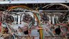
20220820_102158.jpg

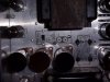
20220820_102211.jpg
 
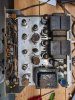
There's room to install the test point jacks between each tube pair. If I'm not mistaken, the first pic above shows the 3.3 ohm resistor coming off the cathode pin of the tube socket, and it should be going to a ground point on the terminal strip. On one pair there's an orange wire connecting both cathodes, and on the other pair it's the orange/white wire. I think all you have to do is remove that common connecting wire on both tube pairs, remove the 3.3 ohm resistors, and then run the 10 ohm resistors off each of the 4 cathode pins to ground. Then just mount the 4 test point jacks on the deck and connect a wire from the tube socket pin to the test point jack. That way you're measuring across the 10 ohm resistor to ground to get your bias level for each tube. I don't know that a ground buss is necessary as I believe that terminal strip where the 3.3 ohm resistor is connected is close enough that you can wire in each of the 4 individual 10 ohm resistors, 2 per side, to that strip's ground lug. At that point the remaining 'bias check' system is essentially useless, and it may be advisable to remove it just so as to 'not' confuse anyone in the future. I don't think there's anything adversely affected by doing so, but maybe check the schemo again just to be sure.
 
There's room to install the test point jacks between each tube pair. If I'm not mistaken, the first pic above shows the 3.3 ohm resistor coming off the cathode pin of the tube socket, and it should be going to a ground point on the terminal strip. On one pair there's an orange wire connecting both cathodes, and on the other pair it's the orange/white wire. I think all you have to do is remove that common connecting wire on both tube pairs, remove the 3.3 ohm resistors, and then run the 10 ohm resistors off each of the 4 cathode pins to ground. Then just mount the 4 test point jacks on the deck and connect a wire from the tube socket pin to the test point jack. That way you're measuring across the 10 ohm resistor to ground to get your bias level for each tube. I don't know that a ground buss is necessary as I believe that terminal strip where the 3.3 ohm resistor is connected is close enough that you can wire in each of the 4 individual 10 ohm resistors, 2 per side, to that strip's ground lug. At that point the remaining 'bias check' system is essentially useless, and it may be advisable to remove it just so as to 'not' confuse anyone in the future. I don't think there's anything adversely affected by doing so, but maybe check the schemo again just to be sure.
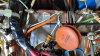
The 3.3 ohm resistors are going to a terminal with other connections to it, not direct ground. So I believe the ground buss has to attach there also, hard to remember clearly. It appears there is a white wire with black tracer going to these terminals and coming from a negative lug of a can cap, this must be where the ground occurs.

20220820_113454.jpg
 
Last edited:
I have modified a few Scott amps of this vintage to provide the individual 10 ohm current sensing resistors.
On the LK72B I found a tidy way to do it, is to strip out the wiring, resistors , capacitors and RCA test jacks used by the original Scott bias adjust system, and use the DPDT slide switch to allow switching between left and right channels when performing the adjustment.
I installed two test point jacks in place of the original RCA jacks and added a third test point to use as a convenient ground point when making adjustments.
When I wired the 10ohm resistors, I used the original ground points that the 3.3 ohm resistors used.
I connected the Ground test point jack to one of locations used by the 3.3 ohm resistors.

The center two terminals of the DPDT switch are connected to the test point jacks, and each pair of slide switch terminals are connected to the cathode terminals on the socket of the tubes being adjusted.
It's really pretty simple if you make a sketch of what you're doing.
 

Attachments

  • LK72B Bias test ponits.JPG
    LK72B Bias test ponits.JPG
    103.9 KB · Views: 23
I have the 4 test jacks installed, removed the wiring, and the 3.3 ohm resistors. Just curious about the center wiring on the switch, orange wire runs up to a terminal in front, and other side to a resistor to ground. Thinking this can stay, or should I remove?

20220820_130901.jpg

20220820_130918.jpg

20220820_131304.jpg
 
With the 4 test points you installed, there's no need to use the switch, since the jacks are permanently wired directly to the Cathodes of both tubes in each channel.
I don't think that there's any harm in leaving the connections on the switch, since the resistors and capacitors are part of the original testing circuit, but I'd remove everything associated with the original circuit to avoid confusion in the future.
 
Back
Top Bottom