

You are using an out of date browser. It may not display this or other websites correctly.
You should upgrade or use an alternative browser.
You should upgrade or use an alternative browser.
How bad is this power supply ringing?
- Thread starter Tubeglowpio
- Start date


primosounds
Powered with pure tube sounds.
Using psud2 is a good tool but it doesn't tell you how the amp will sound. Nor does it tell you how much ringing relates to an audible artifact. I like to use it to "ballpark" my ps components. Where it does well is show you if your tube rectifier is going to be over voltage or over current with the elements in your ps.I'm trying to document these steps because things can change a lot, I think I'm starting to get the hang of using this to check ringing. So I think having that second choke is really screwing up my supply, I think putting the chokes in series looks a lot better. Here is a before and after of that.View attachment 1198686 View attachment 1198687

Tubeglowpio
Active Member
Why do you need two chokes? What ripple voltage are you aiming for? Here's a simpler idea that may achieve your goals just as well. There is zero ring at the current transition at 10 seconds into the simulation. The red trace shown is V(C2).
View attachment 1198854
This has ripple of 73 mv p-p at V(C2) and 5 mV p-p at V(C3). Changing C2 to 220 uF produces ripple of 35 mV at V(C2) and 7 mV at V(C3), according to simulation.
Thank you, I was trying to figure out how it should look in this program. The only time I've seen someone demonstrate ringing was on a o scope and they injected a square wave and looked at the over shoot. A different power supply for another amp gave me this which I thought looked pretty ideal?I don't get your curves as your B+ seems not constant before you apply the load.
Here is what you should aim for: a reduction of B+ under load, but without ringing.
View attachment 1198902

Tubeglowpio
Active Member
So I already have the second choke mounted so would hate to remove it so I figured having it in series with the first choke shouldn't cause any issues correct?
Tubeglowpio
Active Member
how's this then?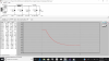
Tubeglowpio
Active Member
It's a rh84 amp build so I've heard they need better regulation than most single ended amps, I think it's due to the plate to plate feedback. I think I was going for less than 10mA of ripple for the outputs in that arrangement.Why do you need two chokes? What ripple voltage are you aiming for? Here's a simpler idea that may achieve your goals just as well. There is zero ring at the current transition at 10 seconds into the simulation. The red trace shown is V(C2).
View attachment 1198854
This has ripple of 73 mv p-p at V(C2) and 5 mV p-p at V(C3). Changing C2 to 220 uF produces ripple of 35 mV at V(C2) and 7 mV at V(C3), according to simulation.
primosounds
Powered with pure tube sounds.
Mounting a choke in series just adds up the inductances . But if you add a capacitor in between each choke you will get more filtering of the B+ and a certain dynamic liveliness which can be more lifelike than a straight pi filter. That is what i feel is the sonic advantage of using 2 chokes.So I already have the second choke mounted so would hate to remove it so I figured having it in series with the first choke shouldn't cause any issues correct?
Tubeglowpio
Active Member
I know that adding both together sounds like the safer route as I would think it would just act like a larger inductor with resistance of course. I was having more trouble getting the two separate choke filter to not ring in the psud2 but your experience with these amps does make me feel better about it. Ive been meaning to ask you about the rh84 schematic as I see each channel actually has their own 10uf cap so I should omit my last cap then. Did you find 10uf for each channel good? I was thinking of using this 400 volt audyn crossover cap, but not sure if it's bad to use a crossover cap in the supply? I might order some solen fast caps but have heard they can sound dry.Mounting a choke in series just adds up the inductances . But if you add a capacitor in between each choke you will get more filtering of the B+ and a certain dynamic liveliness which can be more lifelike than a straight pi filter. That is what i feel is the sonic advantage of using 2 chokes.

how's this then?View attachment 1198918
Yes, much better. No bouncing of the voltage under sudden load.
The faster it recovers the better your amp will by dynamic, or at least not limited by the PS.
I personally start to think chokes are not good for fast reacting PS. I prefer RCRC for that.

Tubeglo,
It depends on what speakers you are going to use with this amp. For a single ended amp, if you were to use the config I posted previously but with a 220 uF cap right after the choke, the noise contributed by the power supply would be about 35 mV peak to peak, or 12 mV RMS. Reflect that through a 5K:8Ω output transformer and the noise contributed by power supply ripple as seen at the speaker terminals would be about 0.5 mV. That might not be low enough if you are listening with 105 dB high efficiency horns. On the other hand if you have 90 dB traditional paper cone speakers, it will probably not be discernible.
I prefer only one choke in the power supply--not too big--max about 3 Henry, as I think it allows the power supply react faster to bass transients, but that's just an opinion. But then again I listen to PP amps where super low ripple is not necessary.
It depends on what speakers you are going to use with this amp. For a single ended amp, if you were to use the config I posted previously but with a 220 uF cap right after the choke, the noise contributed by the power supply would be about 35 mV peak to peak, or 12 mV RMS. Reflect that through a 5K:8Ω output transformer and the noise contributed by power supply ripple as seen at the speaker terminals would be about 0.5 mV. That might not be low enough if you are listening with 105 dB high efficiency horns. On the other hand if you have 90 dB traditional paper cone speakers, it will probably not be discernible.
I prefer only one choke in the power supply--not too big--max about 3 Henry, as I think it allows the power supply react faster to bass transients, but that's just an opinion. But then again I listen to PP amps where super low ripple is not necessary.
Tubeglowpio
Active Member
This amp has 5k 4ohm outputs, the speakers will be about 91db and used in a small bedroom. Ive only used a small choke once in a build, another build was a RCRC. Had no problems with either. I have heard others say too much inductance can have a negative impact on sound. I'm building a 2a3 amp next so will be getting top notch parts for that amp. Already have some ASC caps for the power supply.Tubeglo,
It depends on what speakers you are going to use with this amp. For a single ended amp, if you were to use the config I posted previously but with a 220 uF cap right after the choke, the noise contributed by the power supply would be about 35 mV peak to peak, or 12 mV RMS. Reflect that through a 5K:8Ω output transformer and the noise contributed by power supply ripple as seen at the speaker terminals would be about 0.5 mV. That might not be low enough if you are listening with 105 dB high efficiency horns. On the other hand if you have 90 dB traditional paper cone speakers, it will probably not be discernible.
I prefer only one choke in the power supply--not too big--max about 3 Henry, as I think it allows the power supply react faster to bass transients, but that's just an opinion. But then again I listen to PP amps where super low ripple is not necessary.

trobbins
Super Member
Tubeglo - perhaps take a step back and post a PSUD2 simulation that reflects what the amp is doing at idle (no sound) - using part values that you have measured (ie. transformer winding resistances, and choke series resistances and inductances at the operating DC current, and load current level at idle). Then tell us what you think happens when there is a music transient through the amp, and how you think you can prepare the PSUD2 circuit to show that transient change.
You can set PSUD2 up to show a transient change relating to a step from no signal to full signal, and similarly do a simulation when stepping from full signal to no signal. But you need to appreciate what that means with respect to the loading on the power supply, and then apply that understanding to setting up PSUD2.
You can set PSUD2 up to show a transient change relating to a step from no signal to full signal, and similarly do a simulation when stepping from full signal to no signal. But you need to appreciate what that means with respect to the loading on the power supply, and then apply that understanding to setting up PSUD2.

dowto1000
BANNED
Your filter does not ring on a step test. It has a smooth voltage-transition an a step test, actually too smooth. It is slow as a slug, and is typical, unfortunately, of what is built and used, the last 100 years. You have way over-filtered the B+, as most people do, at the expense of obtaining full dynamics and dynamic contrasting. That becomes another typical boring-to-hear tube amplifier.
The first thing that my then-audio Mentor taught me in 1982 was that all chokes had to be 20 Ohms or less, in DCR, especially with a tube amp using DHTs like 2A3s for the Finals. In the 1990s, the Dean of the EE Department - an audiophile, at a major university taught me to obtain the least possible SERIES resistances in a power supply'a B+ filter to the Finals.
We always use L1/C2/L2/C2 B+ filter in a tube amp design. A "C", right after the rectifier tube, puts spikes on the B+, that a choke avoids. Best of all, the L1 does not ( and should not) meet what is termed in the text books as "Critical Inductance". R/C networks to the Finals are, of course, never to be used.
In 2018, I use the L1 and L2 chokes that are small, and each is 8 Ohms DCR maximum, to the Finals. So, 16 Ohms or less is my design goal in 2018, to the Finals, as a result of choke DCRs. For Cs, never as much as 100 uF, I stay under 56 uF in any one spot. The large uF 'C" will rob the Finals tube of its ability to play dynamic Instantaneous peaks, at circuit recharge time.
All I post has been built and discussed by a handful of builders, some EEs, and it is proven to be unbeatable, sonically, over the last twenty years. The only people who regularly critique this, have simply never ever heard it yet, properly implemented. Such amps with the supply I have outlined got " best Sound At Show" in 2016 from Stereophile magazine, because the reviewer actually LISTENED to it !!
I am not in the audio business, just an avid DIYer, who HAS actually built and heard what I've posted herein, at length, versus conventional " by the book " / artificial sounding tube amp power supplies.
Dowto1000
The first thing that my then-audio Mentor taught me in 1982 was that all chokes had to be 20 Ohms or less, in DCR, especially with a tube amp using DHTs like 2A3s for the Finals. In the 1990s, the Dean of the EE Department - an audiophile, at a major university taught me to obtain the least possible SERIES resistances in a power supply'a B+ filter to the Finals.
We always use L1/C2/L2/C2 B+ filter in a tube amp design. A "C", right after the rectifier tube, puts spikes on the B+, that a choke avoids. Best of all, the L1 does not ( and should not) meet what is termed in the text books as "Critical Inductance". R/C networks to the Finals are, of course, never to be used.
In 2018, I use the L1 and L2 chokes that are small, and each is 8 Ohms DCR maximum, to the Finals. So, 16 Ohms or less is my design goal in 2018, to the Finals, as a result of choke DCRs. For Cs, never as much as 100 uF, I stay under 56 uF in any one spot. The large uF 'C" will rob the Finals tube of its ability to play dynamic Instantaneous peaks, at circuit recharge time.
All I post has been built and discussed by a handful of builders, some EEs, and it is proven to be unbeatable, sonically, over the last twenty years. The only people who regularly critique this, have simply never ever heard it yet, properly implemented. Such amps with the supply I have outlined got " best Sound At Show" in 2016 from Stereophile magazine, because the reviewer actually LISTENED to it !!
I am not in the audio business, just an avid DIYer, who HAS actually built and heard what I've posted herein, at length, versus conventional " by the book " / artificial sounding tube amp power supplies.
Dowto1000
Tubeglowpio
Active Member
It is a class A amplifier so the current shouldn't change much from idle, right? all resistance, cap values, voltages, inductance values and current draw were included. The only resistance I didn't actually measure was the power transformer windings.Tubeglo - perhaps take a step back and post a PSUD2 simulation that reflects what the amp is doing at idle (no sound) - using part values that you have measured (ie. transformer winding resistances, and choke series resistances and inductances at the operating DC current, and load current level at idle). Then tell us what you think happens when there is a music transient through the amp, and how you think you can prepare the PSUD2 circuit to show that transient change.
You can set PSUD2 up to show a transient change relating to a step from no signal to full signal, and similarly do a simulation when stepping from full signal to no signal. But you need to appreciate what that means with respect to the loading on the power supply, and then apply that understanding to setting up PSUD2.
Tubeglowpio
Active Member
Enjoyed your post and I understand what you're saying, I was messing around with this program and found that some simpler power supplies actually gave nice dynamics as that slow curve in mine shown was much steeper. I found that a smaller capacitance in certain areas such as the first cap and smaller inductor values gave better dynamics but at the cost of more voltage ripple. I suppose a lclc would work best as it has better voltage regulation.Your filter does not ring on a step test. It has a smooth voltage-transition an a step test, actually too smooth. It is slow as a slug, and is typical, unfortunately, of what is built and used, the last 100 years. You have way over-filtered the B+, as most people do, at the expense of obtaining full dynamics and dynamic contrasting. That becomes another typical boring-to-hear tube amplifier.
The first thing that my then-audio Mentor taught me in 1982 was that all chokes had to be 20 Ohms or less, in DCR, especially with a tube amp using DHTs like 2A3s for the Finals. In the 1990s, the Dean of the EE Department - an audiophile, at a major university taught me to obtain the least possible SERIES resistances in a power supply'a B+ filter to the Finals.
We always use L1/C2/L2/C2 B+ filter in a tube amp design. A "C", right after the rectifier tube, puts spikes on the B+, that a choke avoids. Best of all, the L1 does not ( and should not) meet what is termed in the text books as "Critical Inductance". R/C networks to the Finals are, of course, never to be used.
In 2018, I use the L1 and L2 chokes that are small, and each is 8 Ohms DCR maximum, to the Finals. So, 16 Ohms or less is my design goal in 2018, to the Finals, as a result of choke DCRs. For Cs, never as much as 100 uF, I stay under 56 uF in any one spot. The large uF 'C" will rob the Finals tube of its ability to play dynamic Instantaneous peaks, at circuit recharge time.
All I post has been built and discussed by a handful of builders, some EEs, and it is proven to be unbeatable, sonically, over the last twenty years. The only people who regularly critique this, have simply never ever heard it yet, properly implemented. Such amps with the supply I have outlined got " best Sound At Show" in 2016 from Stereophile magazine, because the reviewer actually LISTENED to it !!
I am not in the audio business, just an avid DIYer, who HAS actually built and heard what I've posted herein, at length, versus conventional " by the book " / artificial sounding tube amp power supplies.
Dowto1000
Tubeglowpio
Active Member
I'm am in school for ee so still consider myself new to the game, only have a few builds down and was going for the slower but sweet sound on this one, but after working some other example supplies maybe I would actually enjoy a more dynamic yet still sweet amp. ive got a lot of experimenting to do ahead of me.Your filter does not ring on a step test. It has a smooth voltage-transition an a step test, actually too smooth. It is slow as a slug, and is typical, unfortunately, of what is built and used, the last 100 years. You have way over-filtered the B+, as most people do, at the expense of obtaining full dynamics and dynamic contrasting. That becomes another typical boring-to-hear tube amplifier.
The first thing that my then-audio Mentor taught me in 1982 was that all chokes had to be 20 Ohms or less, in DCR, especially with a tube amp using DHTs like 2A3s for the Finals. In the 1990s, the Dean of the EE Department - an audiophile, at a major university taught me to obtain the least possible SERIES resistances in a power supply'a B+ filter to the Finals.
We always use L1/C2/L2/C2 B+ filter in a tube amp design. A "C", right after the rectifier tube, puts spikes on the B+, that a choke avoids. Best of all, the L1 does not ( and should not) meet what is termed in the text books as "Critical Inductance". R/C networks to the Finals are, of course, never to be used.
In 2018, I use the L1 and L2 chokes that are small, and each is 8 Ohms DCR maximum, to the Finals. So, 16 Ohms or less is my design goal in 2018, to the Finals, as a result of choke DCRs. For Cs, never as much as 100 uF, I stay under 56 uF in any one spot. The large uF 'C" will rob the Finals tube of its ability to play dynamic Instantaneous peaks, at circuit recharge time.
All I post has been built and discussed by a handful of builders, some EEs, and it is proven to be unbeatable, sonically, over the last twenty years. The only people who regularly critique this, have simply never ever heard it yet, properly implemented. Such amps with the supply I have outlined got " best Sound At Show" in 2016 from Stereophile magazine, because the reviewer actually LISTENED to it !!
I am not in the audio business, just an avid DIYer, who HAS actually built and heard what I've posted herein, at length, versus conventional " by the book " / artificial sounding tube amp power supplies.
Dowto1000
I suggest you build it the best you know how with your current expertise. There's still a lot to learn even if this amp won't win any awards. The knowledge you will gain from building it will be invaluable. You can apply those learnings to your next build, and so on.
Tubeglowpio
Active Member
Guess I was trying to squeeze a bit more wisdom before I finished wiring up the power supply. This summer I'm taking some time to build a very nice tube amp prototyping board with a bunch of socket boards I picked up and some terminal blocks. That way I can switch out components and move wires around like crazy.I suggest you build it the best you know how with your current expertise. There's still a lot to learn even if this amp won't win any awards. The knowledge you will gain from building it will be invaluable. You can apply those learnings to your next build, and so on.
trobbins
Super Member
My 2 cents:It is a class A amplifier so the current shouldn't change much from idle, right?
If you stay within class A, then the power supply is effectively static with respect to changing conditions coming from each end - mains charging pulses come in one end but effectively don't perturb the other end - and output stage signal currents pass through the filter output cap but don't effectively pass back through the filter to perturb the other end. So chasing power supply filter ringing behaviour is like working on a solution when there is no problem. If your class A is loosing it at peak signal, then you've got other issues to deal with more than the power supply.
If you have a hum level down near the amp's noise floor, then B+ ripple voltage on the output stage may be the dominant hum source, and may be noticeable. If you had a hum 'aim', then it would be to build your amp and work out how to alleviate all the other hum sources to see if you can actually measure and hear the hum from just the B+ ripple - that would then be a good place to start looking further at your B+ supply, and you would be a wiser person for the learning curve taken.
The output stage filter capacitance, although it is part of the power supply, should be located and wired so as to minimise loop area for the output stage signal current path. And as with all filter caps, connect input and output circuits only at the cap terminals.
dowto1000
BANNED
Enjoyed your post and I understand what you're saying, I was messing around with this program and found that some simpler power supplies actually gave nice dynamics as that slow curve in mine shown was much steeper. I found that a smaller capacitance in certain areas such as the first cap and smaller inductor values gave better dynamics but at the cost of more voltage ripple. I suppose a lclc would work best as it has better voltage regulation.[/QUOTE
HI,
You are under the impression that low ripple is important to good sound. It comes at a huge expense, in lackluster and never-real DYNAMICs and dynamic contrasting.
Great sounding 2A3 amps may have high ripple, up to 750 to 850 mVAC of B+ ripple, peak to peak, going to the Finals ( 2A3 SET ). Some of mine do. Driver stage B+ , however, ( mu of 100 tubes ) is SHUNT regulated, heavily, and has under 2 mVAC, peak to peak.
I don't think ripple is too important, in a "common place" circuit you are doing now, but that upcoming SET 2A3 amp of yours - is what I am " mostly" addressing.
it is a TOTAL fallacy to think that a Class A1 operation of a SET negates the need for a really great power supply design. People employing hundred year old techniques ( eg : 10 HY at 100 Ohm DCR Chokes, and high amounts of uFs ) propose this fallacy. These people are mistakenly unaware of what is needed to obtain good, no,... great, ..... tube amp audio performance.
Dowto1000
Last edited: