• The move to the new server is done. There are some software and database maintenance updates in process. This has us passing the hat around to help out. We appreciate any donations. Seriously, even a dollar helps. The payment page may be found here - https://www.audiokarma.org/support.html

How to measure and wire up Infinity EMIT (Quantum 2 )

KraftwrkTrbo

Active Member
I want to measure my 3 (respective 4) EMIT drivers.
What resistance should each measure?
How to wire up
a) 3 EMIT (front facing)
b) 4 EMIT (3 front, one rear)
 
Register to hide this ad
If you can read a schematic or follow a wiring diagram, this might help.
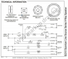
http://www.infinity-classics.de/technik/manuals/Quantum_2_technical_sheet.pdf

I suspect, but not 100% sure, that a resistance reading of around 3.0 to 3.6 would be correct for those EMIT's.
If I'm wrong I'm sure someone will point it out.
I have the wiring diagram, but it does NOT show HOW the 3 (4) EMITS are wired up. Pretty sure for example that they are not all wired in parellel (resulting resistance WAY too low). Pretty sure they are not all wired in series (resulting resistance WAY too high). So that leaves for 3 EMIT: one in series with 2 parelle? and respectively for 4 EMIT (one rear facing): 2 parellel pairs in series?

Also find it strange that there is only ONE wiring diagram circleing around. Concern: a) does not show the binding posts for the bi-amping b) the crossover values IMO should be different for the 4 EMIT version compared to the 3 EMIT version. Which leaves the question: WHICH diagram do we have floating around? The bi-amp or non bi-amp? The 3 EMIT or 4 EMIT?
 
I guess I should have stated "might OR MIGHT NOT" help...you didn't state you already have that diagram, you just asked for help.
Looks like that is Rev. A and dated 7-98. There has been speculation that the "official" schematics are the last version but that has not been verified as far as I know.
Options at this point:
Contact Harmon though I doubt that would do any good.
Wait for an AK'er with intimate knowledge to post either a diagram or images.
Search Google and/or ebay for Quantum 2 crossovers and see if they could be of any help as far as wiring.
Were your speakers unwired when you got them?
When removing more than one wire I have found it's never a bad idea to take pictures, label wires and/or draw a wiring diagram. But then I'm old and can't always trust my memory bank.
 
Previous owner a) did a hack job on the crossovers, trying to rewire for tri amping. In process, created cold solder, solders that broke off, etc. b) previous owner for some reason had ONE speaker with 3, the other with 4 EMITS, and one crossover initially bi-amp, the other not. Rebuilding the crossover, rewiring the speakers (for 3 EMITS (will abandon the one rear facing EMIT), bi amp. Looking at the crossovers don't show how the EMITS are wired (there is only one wire going from the crossover to the speakers, then branching off.
 
Previous owner a) did a hack job on the crossovers, trying to rewire for tri amping. In process, created cold solder, solders that broke off, etc. b) previous owner for some reason had ONE speaker with 3, the other with 4 EMITS, and one crossover initially bi-amp, the other not. Rebuilding the crossover, rewiring the speakers (for 3 EMITS (will abandon the one rear facing EMIT), bi amp. Looking at the crossovers don't show how the EMITS are wired (there is only one wire going from the crossover to the speakers, then branching off.

Wow, sounds like you received a mess.
Hopefully one of the smart folks here can offer you some guidance.
I have to admit any more than bi-wiring makes my brain hurt. Bi-amping makes my head spin.
Good luck, hope you get it all figured out.
 
So that leaves for 3 EMIT: one in series with 2 parelle? and respectively for 4 EMIT (one rear facing)

If they follow the pattern used by later Infinitys with rear tweeters, the rear tweeter will be on its own crossover segment and not wired in with the fronts. It would also have different wire colors from the fronts. Of course this is speculation. It seems the only real way to know is hope someone with intact Quantum 2s can look at their wiring and chime in.

As for bi-amping, it should be relatively easy to split off the wires feeding the woofer section of the crossover and connect those wires to the additional binding posts
 
Just thought to take a look at what was done with the QLS-1 since they also have rear tweeters. The technical sheet shows the rear tweeter being wired into the same part of the crossover as the front tweeters but in reverse phase.
 
As for bi-amping, it should be relatively easy to split off the wires feeding the woofer section of the crossover and connect those wires to the additional binding posts

A friendly helper here had already marked up the wiring diagram to show me where the bi-amp terminals should go: upload_2022-2-11_16-53-6.png
 
Just thought to take a look at what was done with the QLS-1 since they also have rear tweeters. The technical sheet shows the rear tweeter being wired into the same part of the crossover as the front tweeters but in reverse phase.
Does it show the tweeters themselves are grouped/wired? In series, parallel?
 
Just thought to take a look at what was done with the QLS-1 since they also have rear tweeters. The technical sheet shows the rear tweeter being wired into the same part of the crossover as the front tweeters but in reverse phase.
It seems the only real way to know is hope someone with intact Quantum 2s can look at their wiring and chime in.
*blended statements from 2 posts by seifreit

I think the rear tweeter on my RS II's is wired in similar fashion.
http://www.infinity-classics.de/technik/manuals/RS_II_technical_sheet.pdf
I agree it would be GREAT if someone here who has Q 2's would post pictures and/or a wiring diagram.
 
Done with redoing the crossovers (set up for bi amping).
But now facing the driver re-wiring.
a) How are the 3 (and 3+rear) EMIT wired?
b) How are the 2 'dome midrange' wired?
 
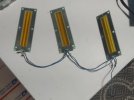
Here are two images for the Q2. One are the original crossovers pulled out and photographed before I reworked them. It shows original wires color coded which corresponds to the Infinity crossover schematic. The other photo shows how the tweeters were wired (parallel). My pair did not have the rear tweeters but did have the cutout and grill where they would go. It is my understanding, based on research online, rear tweeters were an option for the Q2 and the dealer would install rear tweeters if the owner wished. I used the QLS1 schematic as a reference as how to wire the Dayton Audio rear tweeter I installed on my pair. Hope this helps
 

Attachments

  • Q2crossovers_org.jpg
    Q2crossovers_org.jpg
    67.3 KB · Views: 10
  • Q2tweeters.jpg
    Q2tweeters.jpg
    66.6 KB · Views: 9
Back
Top Bottom