• The move to the new server is done. There are some software and database maintenance updates in process. This has us passing the hat around to help out. We appreciate any donations. Seriously, even a dollar helps. The payment page may be found here - https://www.audiokarma.org/support.html

I just received a nice Sansui AU-719 for restoration

richiem46

Retired and enjoying life and music!
Subscriber
I have previously restored a Sansui AU-717 and a AU-919 and both went well. I must really enjoy removing the notorious Sansui glue because I just purchased an AU-719 from a gentleman in Canada. It looks clean and appears to be all original. It powered up normally and came out of protection. I checked the bias and it was slightly off so I adjusted it and it was steady on both channels. The DC offset was a little high on the right channel so I adjusted it. The DC offset adjustment was very "touchy", even more so than on the AU-919 I restored.

Once the adjustments were made I connected some speakers and had a listen. The AU-719 played quite well which pleased me of course! I just ordered restoration kit from Affinity for artifacts and supplemented that with multi-turn bournes trimmers to hopefully address some of the adjustment sensitivity. Once I receive all of the parts I will start my deasoration and document my progress here. Looking forward to getting started!

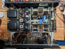
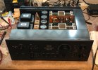
Here are a few pictures of the AU-719 in it's present state:
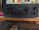
PXL_20260722_200751010.jpg

PXL_20260722_200810116.jpg
 
Register to hide this ad
You will not have any issues since you have restored the 717 and 919. Less glue on the 719 but watch out for the black flags on the driver board. If you plan to change VAS transistors make sure they have a low COB replacement. Should be a fun restoration. Please provide updates as you progress with the restoration.
 
A brief update: The restoration kit from Affinity for Artifacts arrived today and the Bournes trimmers will arrive tomorrow. I will begin the restoration probably on Wednesday. I was listening to the AU-719 tonight with a pair of JBL L-36 speakers that I restored and i have to say I really like the sound of this unit even in it's un-restored state.

Looking foreward to getting started!
 
The AU719 is a nice amp. I am a bit disappointed that Sansui omitted the internal covers on this model, though I understand why.

Mine also had the transformer covers, but again, I was a bit disappointed that they don’t have the Sansui logo on them like the AU-517/717.

That said, the AU-719 chassis is set up for the internal covers, and the covers from the 517/717 fit nicely with only having to extend one wire. (From what I remember)

And, the 517/717 transformer covers fit as well.

How do I know?

Here is mine.

Sorry, I like to post it whenever I can.
IMG_5971.jpeg
 
Nice 719! I have one I did a partial restoration & repair on a couple years ago, did all e-caps, glue removal & the black flags plus replaced all output drivers with matched Sankens.

Tip for you depending on how far you go with the resto... I found that the power and EQ boards dont have to be fully removed to get at all the caps & most other parts, I was able to unscrew the mounting screws & slide the big filter caps still in their clamps enough to lift the boards up or away to get access to replace caps. I didnt want to unsolder/unhook all the wires and the filter caps measured within tolerance for capacitance so I left them alone for now. Just a suggestion if you arent going to remove everything to save some work.

I really like the black covers on the 719, mine was a later production so doesnt have any, but Im looking for some from a parted out 717/517.

Good luck on the resto!
 
Tip for you depending on how far you go with the resto... I found that the power and EQ boards dont have to be fully removed to get at all the caps & most other parts, I was able to unscrew the mounting screws & slide the big filter caps still in their clamps enough to lift the boards up or away to get access to replace caps. I didnt want to unsolder/unhook all the wires and the filter caps measured within tolerance for capacitance so I left them alone for now. Just a suggestion if you arent going to remove everything to save some work.

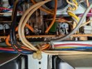
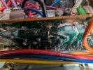
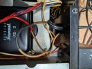
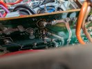
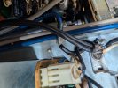
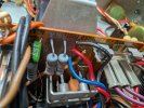
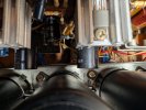
I was looking over my 719 tonight to get my bearings on the layout of things etc. It looks like the 719 power board was removed and worked on previously. A lot of connecting wires were unsoldered or cut and then re-soldered afterwards. The red wire from one of the main filter caps attached to position 10 on the board wobbled when I tiuched the wire side, I guess it was sorta making connection because the amp worked but I re-soldered it as a intermittent connection there would almost certainly take out the outputs and who knows what else on the driver boards. I am attaching a few pictures of what I found thus far. Hard to determine at this point but it looks like the outputs on one channel may have been touched. It is difficult to tell due to the way the TO-3P transistors are mounted. I will have to examine them and the power/driver boards to determine what work was done and why. I have on-hand Sanken 2SC4468-ND/2SA1695-ND transistors to use as replacements in case I encountered any surprises.
Will see what tomorrow brings.......

PXL_20260729_215808253.jpg

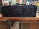
A picture of the AU-719 with the rack handdles installed.

PXL_20260730_014211363.jpg

Some of the re-soldering work on the power board.
PXL_20260730_014218609.jpg

The #10 solder connection I mentioned previuosly.

PXL_20260730_014934321.jpg

Not sure why the transformer primary was cut and then spliced.....will clean this up.

PXL_20260730_015204803.jpg

Another picture of position #10.......
PXL_20260730_015543727.jpg

More mystery splices and solder work...
 

Attachments

  • PXL_20260730_015156252.jpg
    PXL_20260730_015156252.jpg
    128.9 KB · Views: 8
May be the transformer was changed at some point? Do you see splicing on both transformers or just one? The joints look horrible (not enough temperature on the iron). I would get the power board out along with the main filters and start with a clean slate. Refurbish the PSU board, rework all the point to point wiring and add new wire as needed while maintaining the same color. I have pictures with wires marked, happy to share if you need it
 
It looks like the transformer wire was cut in error. My plan is to completely re-build the PSU board and replace the main filter capacitors. Tough to see what else was done to the PSU buard but based on what I have seen so far a clean start is the way to go with the board for sure. I will start working on it tomorrow and post my progress as I go forward.
 
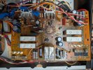
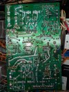
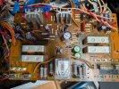
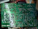
I removed and re-capped the F-3101 power supply ans Protector Board. Removing it was more challenging then it should have been as C607 and C608 would not fit through the chassis slot downward. I managed to remove them from the board and then was able to get it through and work on it. There was some gloe but it wasn't too bad. I soaked it is acetone for 10 minutes and most of it scraped right off. I still have to replace some of the transistors and a few resistors. While I have the board out I will also relpace the 2SF656 SCR that often causes problems in the Sansui protection circuits. Here are a few "before" pictures.


PXL_20260731_135654541.jpg

C607 and C608 in the way.......

PXL_20260731_150901395.jpg

The Sansui Glue........

PXL_20260731_142429653.jpg

Bottom View of the board
 
I was thinking of C615 polarity marking incorrect on PSU/Protector board.

Yes thats the ones I meant, c614 & c615 are marked wrong on the board but are installed correct... so just be sure to put them back the same way they were & ignore the printed polarity.
 
I finished restoring the F-3101 power/protection board and also replaced the four main filter capacitors with 15,000 UF 63V units. in addition to the re-cap I replaced transistor TR606 with a MJE15032G and TR613 with a MJE15033G. I replaced Tr608, 609 and 612 KSC2383 transistors and TR607, 610 and 611 with KSA1013 transistors. These transistors had been previously replaced but since the replacements were included in the kit I installed them. I confirmed the EDB alignment of the new transistors. I replaced Zener diode ZD601 and ZD602 with the replacements included with the kit. D603 was replaced with two 1N4148 diodes wired in series. I also replaced the relay as it was included with the kit though the old relay looked perfectly fine. I had to clip off one set of pind on the relay for it to fit onto the board.

PXL_20260803_000836548.jpg


Here is a botton view of the board after I restored it:

PXL_20260803_000804100.jpg
 
I carefully re-installed the board and connected back all of the wires I had removed and labeled and after double-checking everything I Plugged the AU-719 into the DBT with a 75W bulb installed, crossed my fingers and powered it on. The bulb glowed brightly and then dimmed down to the point where it was barely glowing and the AU-719 came out of protection. I checked the DC offset and all was good. I was very pleased and then powered up the AU-719 on the A/C main and it came out of protection. I then hooked up some speakers and a DAC to the AUX input and eagerly awaited the music to play, but alas.........silence. I confirmed everything was connected properly but nothing on any input.......

Since the protection side of things was working as expected I assumed there was some issue with the power supply side. I got out the meter and started checking voltages and read the expected 32V on terminal 15 but only about 6V on terminal 17. This explained why the pre-amp section was not functioning. With the after pictures I took I was able to determine that the transistors, diodes and capacitors were installed in the correct orientation without removing the board.

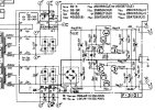
I looked over the schematic and will assume that one of the transistors I used as replacements was defective or out of spec or I installed the wrong transistor in the wrong spot..
I will focus on TR610, TR611, TR612, and TR613 as they are the regulators for the terminal 17 side.

Unfortunately, I will probably have to remove the board to access them. I will use KSA992 and KSA1845 transistors as replacements as I have them on-hand and others have used them successfully as replacements here. I suspect TR613 is not the issue but I will check it of course.

Will work on it tomorrow........


F03101 schematic snippet.jpg
 
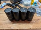
One more thing, here is a picture of the four main filter caps I removed. I left my ESR meter in Florida but it looks like there is some buldging on two of the caps.


PXL_20260804_184631846.jpg
 
An update: I was reviewing my photos of the F3101 board again tonight and realized I missed the problem: TR612 is installed backwards........

I will remove, test and if it is okay re-install it correctly. If it is bad I will replace it.
 
Back
Top Bottom