• The move to the new server is done. There are some software and database maintenance updates in process. This has us passing the hat around to help out. We appreciate any donations. Seriously, even a dollar helps. The payment page may be found here - https://www.audiokarma.org/support.html

I just received a nice Sansui AU-719 for restoration

Another follow-up. I removed TR612 and tested it and tested ok. I then re-installed it and powered the AU-719 up on the DBT with no issues. The voltage on terminal 17 now reads normal!:jump: I then powered up the AU-719 on the mains and checked the bias and DC offset which were fine. I then attached speakers and an audio source on the AUX and played some music. I immediately noticed a difference, the Bass was much more authoritative (it wasn't bad before). I guess the main filter caps were in need of a refresh.

I losened the F3101 board and removed TR613 with it's heatsink to gain clearer access to TR612 so I did not have to remoce the board which greatly pleased me.

I will work on the driver boards next........
 
I restored the first driver board in the AU-719 over the last 2 days. What a pleasure removing it compared to the Power/protector board, just some screws and three connectors to unplug!

I replaced all of the electrolytic caps on the board plus C03 the Black Flag capacitor. The 1UF electrolytics were replaced with 1UF Wima caps. Fuse resistors R04 and R05 were replaced. TR02-TR05 were replaced with KSC1845 transistors and TR06-TR09 were replaced with KSA992's. Zener diodes ZD01 a 27V Zener diode and ZD02 a 13V Zener diode were replaced and ZD03 was replaced with two 1N4148 diodes in series. I also replaced resistors R45 and R46 based on the recommendation od another AK'r. I replaced Trimmers VR01 with a 100 ohm Bourns multi-turn and Vr02 with a 500 ohm Bournes. I replaced the mica/silicone grease on the driver and output transistors with silpads. I noticed that theinput connector socket had a suspect connection on one of the pins and so I re-flowed it.

I cleaned up the rosin on the back of the board and re-installed it in the AU-719, powered up on the DBT and everything looked good. I set the bias and DC offset (DC offset still very touchy) and then plugged the AU-719 into the mains and re-touched the bias and DC offset. I hooked up some speakers and played some music for several hours last evening while re-organizing the garage a bit. The AU-719 played perfectly for the entire time. I will restore the other board over the next day or so.

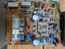
Here ia an "after" picture of the Driver board:

PXL_20260810_014708317.jpg

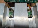
Here are the output transistors with the silpads installed:
PXL_20260810_013444287.jpg
 
Yesterday I restored the second driver board from the AU-719. The process went smoothly and more quickly than the first board since I was familiar with the board logistics after restoring the first board. The list of components replaced is the same as on the first board so I will not detail them here.

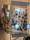
Here is a before picture of the board after I removed it:

PXL_20260811_201638566.jpg


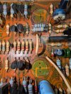
Fortunately there was not too much of the Sansui Glue on this board:

PXL_20260811_202214207.jpg


I used the Acetone 10 minute soak and scrape technique to remove the glue:

PXL_20260811_202755331.jpg

Here is a picture of the board after cleaning using a flat bamboo skewer section to scrape off the glue. The bamboo does not scratch the board.

PXL_20260811_204258767.jpg


I was amazed at how dirty the board connectors on both driver boards were. I cleaned them up before re-installing them.

PXL_20260811_201608885.jpg

After re-installing the second driver board I powered the AU-719 up on the DBT and everything looked okay. I set the bias and DC offset reasonably close to their specifed values. The DC offset on this board was initially over 1 volt before I dialed it down. I was kind of surprised the board came out of protection with the offset that high. The offset setting was as touchy as ever.

I then powered the AU-719 up on the mains and re-touched the bias and DC offset.

Hooked up some speakers and a music source to the AUX input and listened to music for about an hour. With both driver boards restored the music seemed a bit more smooth for lack of a better word. I didn't expect much of an impact after restoring the driver boards but the AU-719 just sounded more "pleasant" afterwards, subtle but noticeable if that makes any sense.........

I am taking the rest of the week off to prepare for company on Saturday to celebrate my 75th Birthday. I will restore the remaining two boards starting on Monday.
 
Well after a significant delay caused by me being sidetracked by issues with a Sansui G8700-DB that I had a fellow AK'r ship to me. ( it was smashed in shipment but insurance made good on the damage after a bit of bureaucracy). More on that in another post......

I restored the AU-719 Tone board yesterday afternoon finally. I replaced all of the electrolytic capacitors and all of the transistors on the board as most of the transistors were known to be problematic. I was able to easily access all of the components without removing the board which was nice.

Here is a picture of the board after I restored it:

PXL_20261004_160725584.jpg

I played the AU-719 for several hours last night and though the sound of the amp improved after the restoration. It was not a "night and day" difference but definitely better. I was quite pleased with the results.

The final board I have to restore is the head amp board which will require some disassembly of the AU-719 to access.
 
I worked on the head amp board last night and made good progress. I restored one channel and will do the second one probably today sometime.

I have a question though, there are two trimmer pots on this board VR01 and VR02. You are suppose to adjust them for 0V on the two test points. My question is how are you suppose to access the two trim pots to adjust them when the board is installed in the chassis? Access to the trimmers is blocked when the board is re-installed in the AU-719 or am I missing something?

Thanks for any insight anyone may have......

PXL_20261005_202927921.jpg
 
IIRC there's a hole on the back side of the board aligned with the pot adjustment?

Reaching the test points was a bit of a challenge though.
 
I have a question though, there are two trimmer pots on this board VR01 and VR02. You are suppose to adjust them for 0V on the two test points. My question is how are you suppose to access the two trim pots to adjust them when the board is installed in the chassis? Access to the trimmers is blocked when the board is re-installed in the AU-719 or am I missing something?

Thanks for any insight anyone may have......

Nevermind......I found the two adjustment holes and fortunately I have a screwdriver that fits through them to adjust the trimmers.
 
I finished restoring the head amp board this afternoon and re-mounted it in the amp tonight. I still have to re-mount ther input assembly on the back panel and re-install the front panel but that will wait until tomorrow in the daylight. Here is a picture of the restored board before I re-installed it:

PXL_20261007_011613542.jpg

I replaced eight fuse resistors on this board that were included in the kit. I tested each resistor I removed to see if they were out of spec but they were all spot-on. When I restored an AU-717 every one of the fuse resistors were either open or way out of spec. I guess they used highter quality parts in this AU-719.
 
I finished re-installing the head amp board in the AU-719 yesterday. The process went smoothly and I then powered up the unit through the dim blub tester and all was well. I then powered up the SU-719 on the mains and went to adjust VR01 and VR02 for 0V on the two test points. Fortunately the two metal test points protruded out of the back of the board far ehough so I could attach a mini-grabber lead to them to measure the voltage. Like the bias and DC balance measurements the VR01 and VR02 adjustments wee VERY touchy. I was able to get them within 20MV of zero which is within the 0-50MV specification. Once that was set I connected a Sansui turntable to the AU-719 to see how the Head Amp was performing. I played the entire Van Morrison Album Moondance as well as the Eagle's Hotel California album. I was very pleased with how the AU-719's phono section sounded, very pleasant and easy on the ears for sure.

Here is a picture of the setup in my garage:

PXL_20261008_001659259.jpg

Overall I really like the sound of the AU-719!
 
Back
Top Bottom