
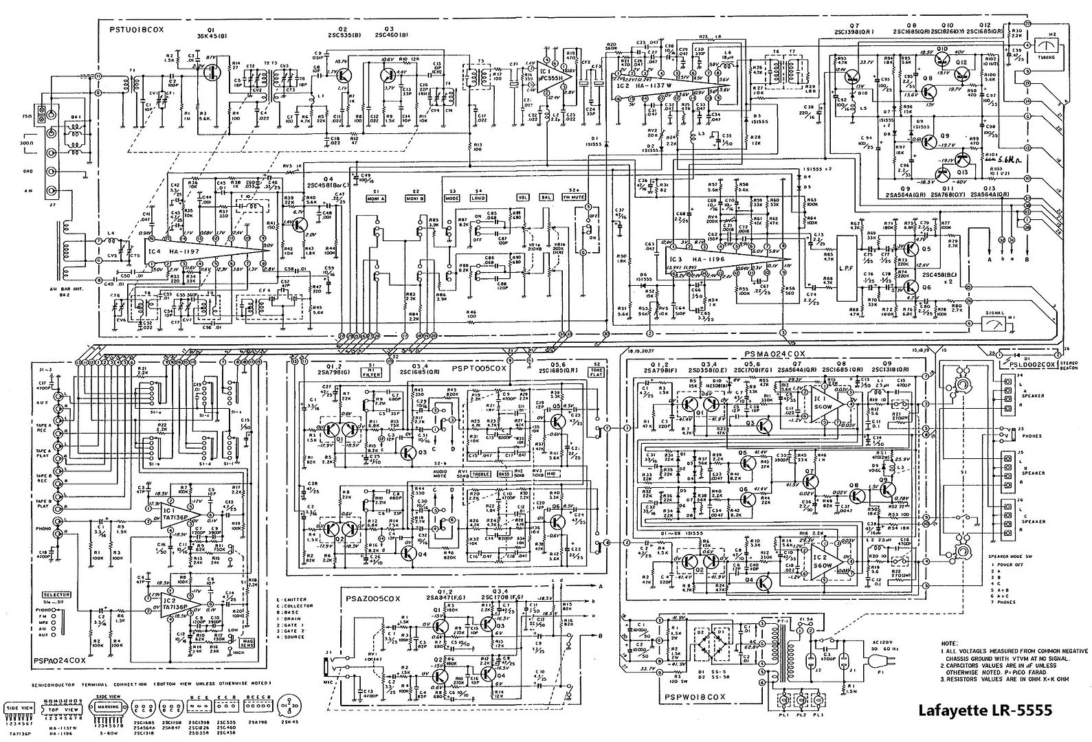
Can you scan the schematic and post it? It would be most helpful for this thread.My schematic is on one 8x11 sheet of paper and I can’t see it! Getting old.
Thanks!



Can you scan the schematic and post it? It would be most helpful for this thread.My schematic is on one 8x11 sheet of paper and I can’t see it! Getting old.
Post #11 has 150-160mV at the pin 4's.What are the voltages at R19/R20?
This is the output (pin 4)

That’s it. I have to use my cellphone camera as a microscope to look at it. But it has everything needed. What happened is everything was working but the 10000 mfd power supply caps were both down to just around 5900 mfd. when I put new caps in the weak transistors at Q7, Q10, and Q11 took a dump. They all were already heat stressed and had the black leg syndrome. It also took out D7. I have new components on the way. This circuit feeds the tuner and the safety circuit. That’s why the relay wasn’t picking upFound it.
That is one complicated puppy! Click on the image to enlarge.
I checked the power packs and they seem to be within spec. I did find the voltage differential transistors in the safety circuit were open.the voltages are listed so this might be easy to narrow down.
What are the voltages at R19/R20?
This is the output (pin 4) of the power packs. the resistors might be easier to measure if your eyes are suspect.
I will measure R19 and R20 tomorrow. Been painting the living room all day. Just a little worn out. I appreciate everyone helping. I took a 15-20 year break from working on electronics and I’m very rusty. Not to mention old!the voltages are listed so this might be easy to narrow down.
What are the voltages at R19/R20?
This is the output (pin 4) of the power packs. the resistors might be easier to measure if your eyes are suspect.
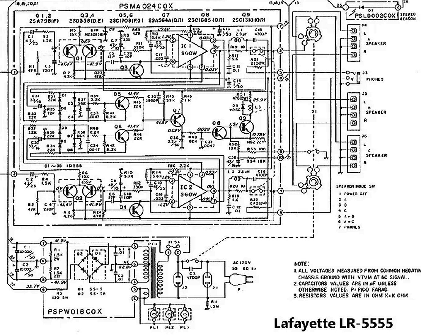


I will measure R19 and R20 tomorrow.
I’m sorry. I did answer that. 150-160 MV. I didn’t realize R19 and R20 were connected to pin 4. I measured straight at pin 4. I was looking at the back side of the board. This unit doesn’t come apart easily for service.Let's see what the new parts do. @mbz said you answered this in post #11
Thank you for the information. It’s most appreciated.Should you stumble upon and wonder...though it's also slightly confusing - schematics states 5,6K not 56K.
View attachment 3837011
A bit more info/files...
View attachment 3837012
I have already looked at the Setton schematic too. They are the same circuit....AI suggests the receiver was built by Setton and is identical to the Setton RS 440. You might want to download documents (owners, service, schem, test and what not the sites carry) about it as well to cross-check it; perhaps there's additional useful info to be found.
View attachment 3837023
I just wanted to clarify that the transistors I found bad are on the tuner board. I’m hoping I don’t have anything wrong on the amp board. I’ll need to check. It’s showing good on pins 1 and 4 of the power packs. The amp board is hard to troubleshoot without desoldering the output modules and removing the board from the heatsink. I’ve already done it twice and don’t want to ruin the traces.
Here's a close-up of the power supply and output stage, if that helps.
I just wanted to clarify that the transistors I found bad are on the tuner board. I’m hoping I don’t have anything wrong on the amp board. I’ll need to check. It’s showing good on pins 1 and 4 of the power packs. The amp board is hard to troubleshoot without desoldering the output modules and removing the board from the heatsink. I’ve already done it twice and don’t want to ruin the traces.
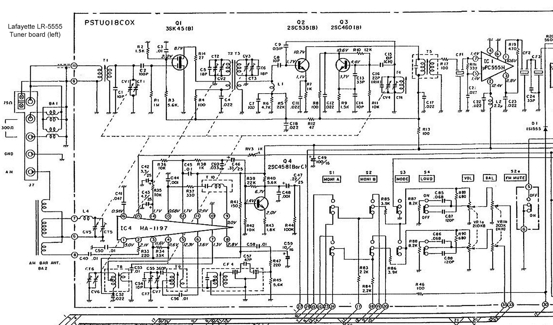

I truly appreciate your support. I just finished taking the amp board apart again and found Q1 and Q2 are both completely open. These will definitely keep the safety relay from latching. I have modern replacements on the way. These are the 2SA798 5 leg transistors. I’m assuming since every component I found open and had black leg disease that the new power supply caps were too much for them. The original caps were very unhealthy and only displayed half their original value.
________________________________________
You are welcome! Are those Hitachi ICs okay? Are they even available anymore?I truly appreciate your support. I just finished taking the amp board apart again and found Q1 and Q2 are both completely open. These will definitely keep the safety relay from latching. I have modern replacements on the way. These are the 2SA798 5 leg transistors. I’m assuming since every component I found open and had black leg disease that the new power supply caps were too much for them. The original caps were very unhealthy and only displayed half their original value.

