• The move to the new server is done. There are some software and database maintenance updates in process. This has us passing the hat around to help out. We appreciate any donations. Seriously, even a dollar helps. The payment page may be found here - https://www.audiokarma.org/support.html

I need help with a power supply problem.

You are welcome! Are those Hitachi ICs okay? Are they even available anymore?
They seem to be fine. I cleaned the black off the legs with an artist brush. They were working before. I’ve narrowed everything down and ordered the parts I need. All the transistors on the amp board are fine besides the Q1 and Q2 five leg ones. I have modern replacements on the way. I had three transistors and one zener diode bad on the tuner board. Everything that went south had the black leg disease. I’m replacing a couple more just for good measure.
 
All the transistors on the amp board are fine besides the Q1 and Q2 five leg ones. I have modern replacements on the way
Seems like you are still working on the amp board, yes replacing those 5 leg transistors with a hfe matched pair will reduce the dc offset from 160mV to below 50mV hopefully, ideally below 10mV however I doubt the 160mV is the cause for protection. Suggest troubleshoot the protection circuit, see post #12.
 
Seems like you are still working on the amp board, yes replacing those 5 leg transistors with a hfe matched pair will reduce the dc offset from 160mV to below 50mV hopefully, ideally below 10mV however I doubt the 160mV is the cause for protection. Suggest troubleshoot the protection circuit, see post #12.
I guess I’m confused. Q1 and Q2 are both burned completely open and everything else on the board passes. These two double transistors being open will keep the relay from closing. These are the voltage differential circuit. Maybe I’m reading the schematic wrong though. I appreciate any help I can get.
 
If the diff amp stage on the power amp board is open it won't pass signal and the offset is liable to be any random voltage between 0 and basically rail voltage. If thats one of those dual transistors you can sub it with two, but ideally you want to stick them together with some heat shrink or whatever to keep them at the same temperature for tracking purposes. If they heat differently the offset will tend to wander as a result. I've also seen an SMD to through-hole adapter using some modern SMD dual transistor sold as a replacement for the original. I don't recall if it was someone on here that made them, or if I saw it on ebay but the only one of these I've had to do got a pair of whatever individual transistors with matched Vf and HFE, as best I could do with my tester and supplies of parts on hand. It worked out fine with low millivolts of offset.


whoever numbered the parts on this thing should be scolded. There are multiple Q1 in here, one per-board. Better practice is to have unique numbering everywhere. Common way to do it is do say 100 series is this board, 200 series is another board, etc.
 
If the diff amp stage on the power amp board is open it won't pass signal and the offset is liable to be any random voltage between 0 and basically rail voltage. If thats one of those dual transistors you can sub it with two, but ideally you want to stick them together with some heat shrink or whatever to keep them at the same temperature for tracking purposes. If they heat differently the offset will tend to wander as a result. I've also seen an SMD to through-hole adapter using some modern SMD dual transistor sold as a replacement for the original. I don't recall if it was someone on here that made them, or if I saw it on ebay but the only one of these I've had to do got a pair of whatever individual transistors with matched Vf and HFE, as best I could do with my tester and supplies of parts on hand. It worked out fine with low millivolts of offset.


whoever numbered the parts on this thing should be scolded. There are multiple Q1 in here, one per-board. Better practice is to have unique numbering everywhere. Common way to do it is do say 100 series is this board, 200 series is another board, etc.
I agree. The transistor numbers on the amp board doesn’t match the schematic either. I ordered these off eBay to replace them. https://www.ebay.com/itm/115598510998
Hopefully after I receive all my parts and get them installed I’ll have a nice unit. It’s in almost mint condition cosmetically. Thanks for the support.
 
yep, those are the things I had in mind.
They should be better than the original ones. I also ordered kits from the same guy for my SS5 and SS5R rectifier modules too. He has good stuff.


straight to tech support jail for whoever did that. Thats just adding insult to injury.
 
I like those replacement transistors. I've had to replace many of these dual transistors lately.

I'm going to get those in my cart.
 
150-160mV is uncomfortably high for my altecs but I don't see it tripping protection, happy to be corrected.

The usual next step is to look at the protection circuit, it's fed by the power amp rail so relay power should be ok.
Suggest work back from the relay drive transistor Q9, measure dc voltages at base then emitter, want Vb = Ve + 0.6V (ON state).

If Q9 is ON then look at R51 (open?)

If Q9 is OFF then check Q8 b, e voltages,
wanting Ve > Vb (OFF state)

Also check Q7 b,e voltages
wanting Vb > Ve (OFF state)

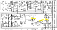
Unfortunately my schematic doesn’t have the same transistor and resistor numbers. Mine has Q11,Q13,and Q15 on the relay circuit.
 
These are the transistors of interest
There we go. That looks familiar. Thank you. I will have to wait until I have the new components installed to measure actual voltage. But all of those transistors check good with a semiconductor tester. And the resistors all check good. R51 is pretty beefy.
 
  • Like
Reactions: mbz
Back
Top Bottom