• The move to the new server is done. There are some software and database maintenance updates in process. This has us passing the hat around to help out. We appreciate any donations. Seriously, even a dollar helps. The payment page may be found here - https://www.audiokarma.org/support.html

I need help with a power supply problem.

These are the transistors of interest
I think I’m giving up on this one. The output modules test good. I replaced everything bad. The tuner works now but the safety circuit still doesn’t. I’m getting supply voltage at the outputs. I’m just too old to be able to do this anymore. I can’t think straight.
 
Take a break.

I have a couple too
My schematic is for the wrong amplifier board so it’s making it terribly difficult to troubleshoot. My board number is PS-MAO24COX. The schematic I have is PS-MAO28COX. My output modules test good but I have 41vdc on pin one of both pin one traces with the modules removed. The differential circuit is off somewhere. I replaced the 2SA798’s with two KSA992’s wired properly. Or so I thought.
 
My schematic is for the wrong amplifier board so it’s making it terribly difficult to troubleshoot. My board number is PS-MAO24COX. The schematic I have is PS-MAO28COX. My output modules test good but I have 41vdc on pin one of both pin one traces with the modules removed. The differential circuit is off somewhere. I replaced the 2SA798’s with two KSA992’s wired properly. Or so I thought.
That was supposed to say I have +41vdc on pin 2. Pin 1 is vcc+. It’s supposed to have 41vdc.
 
Sometimes
That was supposed to say I have +41vdc on pin 2. Pin 1 is vcc+. It’s supposed to have 41vdc.
I had forgotten Mr. Boochie had posted the correct schematic. Hopefully I can narrow it down now. I sure aren’t as efficient as I once was. I think I’ve pulled and tested almost every component on the amp board and cannot figure out why my safety circuit is faulted. Oh well, I’m not giving up.
 
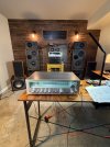
Well, it’s all working now after many hours of chasing a goblin I shouldn’t have chased. It all came down to losing my 0 volt reference on the amp board. The screws that mount the amp board on the heatsink, which then mounts to the chassis, wasn’t making good contact. I put fresh solder on the pads of the board where the screws mount and everything is great. Listening to FM stereo in my underground basement workshop. This tuner has excellent reception. Thanks to all who helped. Below are pictures.
Jon Fox
 

Attachments

  • IMG_6278.jpeg
    IMG_6278.jpeg
    242 KB · Views: 15
  • IMG_6277.jpeg
    IMG_6277.jpeg
    252.1 KB · Views: 15
  • IMG_6276.jpeg
    IMG_6276.jpeg
    252.9 KB · Views: 15
ew, its using the screws as the ground path? Thats janky. I might consider adding a wire from there back to the 0v point in the power supply just to make sure that can't become a problem again.
 
ew, its using the screws as the ground path? Thats janky. I might consider adding a wire from there back to the 0v point in the power supply just to make sure that can't become a problem again.
I already did that. Don’t want anymore problems.
 
Back
Top Bottom