• The move to the new server is done. There are some software and database maintenance updates in process. This has us passing the hat around to help out. We appreciate any donations. Seriously, even a dollar helps. The payment page may be found here - https://www.audiokarma.org/support.html

Is this part difficult to find? (RCA solder board)

The copper braid (uninsulated) is a shield. It catches EMI and drains it back to the TT's ground. The braid shields the signal wires.
The shield is not connected to the RCA plug's ground.
The two insulated conductors in the cable are for the cartridge's signal (R) and ground (W).
The fifth terminal is Ground. You should run a separate wire (green) out from that terminal to the input of your phono stage.
It can be argued that the green wire is redundant...and it probably is. That seems to depend on the turntable. On my turntable(s), the ground wire has continuity with the center spindle. It seems to drain static charges that develop on the surface of the spinning vinyl. Without the green wire...some people get hum, I hear static during playback.
 
If running MM, careful with W2552 as capacitance to shield is quite high at 90pF/m.
 
VM95 likes a bit of capacitance - about 300pF total is ideal with a 47k load.
 
VM95 likes a bit of capacitance - about 300pF total is ideal with a 47k load.
Sheesh, this is all new to me… will the RCA cables I am looking for say 300pF and 47k load on the package or is this something I have to look for online to get the specs of? Any chance you could share a link of whatever RCA cables have these exact specs? It would be greatly appreciated… thank you regardless for the info!
 
Resistive load comes from the phono stage - 47k is the standard for MM, so not something you'll need to worry about. Capacitance is from the wiring in your arm, the interconnect from the 'table to your phono stage, and the phono stage itself - they all add up. It's not going to harm anything, but different loads will manifest as differences in frequency response from the cartridge.
 
Resistive load comes from the phono stage - 47k is the standard for MM, so not something you'll need to worry about. Capacitance is from the wiring in your arm, the interconnect from the 'table to your phono stage, and the phono stage itself - they all add up. It's not going to harm anything, but different loads will manifest as differences in frequency response from the cartridge.
So should any of the three cables listed above in the Mogami link perform just about the same? My 5 lug strip just arrived and I’m all ready to buy some new RCA cables to solder to it and see if I can get this machine running again. Any advice on what the best cables may be for the VM-AT95E/H? What’s a good website or store to get them from?
 
So should any of the three cables listed above in the Mogami link perform just about the same? My 5 lug strip just arrived and I’m all ready to buy some new RCA cables to solder to it and see if I can get this machine running again. Any advice on what the best cables may be for the VM-AT95E/H? What’s a good website or store to get them from?

Most people go as low capacitance cable as reasonable as you can always add capacitance later, whether via loading options in the phono stage, or Y splitters with loading plugs. I've no idea what's ideal for you as I don't know the capacitance of the wire inside your tonearm nor your phono stage, and phono stages capacitance isn't what's written on the tin more often than not.

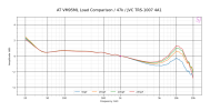
This is what the response of a VM95ML looks like with different capacitance. EN should be similar and the overall trend will be the same.

AT VM95ML Load Comparison_47k_JVC TRS-1007 4A1.png
 
Most people go as low capacitance cable as reasonable as you can always add capacitance later, whether via loading options in the phono stage, or Y splitters with loading plugs. I've no idea what's ideal for you as I don't know the capacitance of the wire inside your tonearm nor your phono stage, and phono stages capacitance isn't what's written on the tin more often than not.

This is what the response of a VM95ML looks like with different capacitance. EN should be similar and the overall trend will be the same.

View attachment 3262971
So I ended up grabbing these… is there any way I can find info on the capacitance of these cables specifically?
 

Attachments

  • IMG_4165.png
    IMG_4165.png
    116.2 KB · Views: 5
0.1nF is 100pF, so not enough resolution. Most DMM with a capacitance function can’t read low enough and aren’t capable of measuring cables reliability. I’ve seen more than a few with a footnote on the spec that says for capacitors only.
 
Back
Top Bottom