• The move to the new server is done. There are some software and database maintenance updates in process. This has us passing the hat around to help out. We appreciate any donations. Seriously, even a dollar helps. The payment page may be found here - https://www.audiokarma.org/support.html

JBL 4333a/Sansui EC138

Following is the Nelsen Pass L300 crossover schematic and I want to copy the midrange section of it. This one is for a 16ohm mid horn . The one I have is an 8ohm 2425. What changes do I need to make to make this work with 8ohms ?

Add a 5-6 ohm resistor inline ( in series ) with your 8 ohm driver ( right at the 2425H drivers terminal > which terminal doesn't matter ).

:)
 
@EarlK Thanks!!
If it's not too much to ask, would you also know how to pad down the 3107 HF (crossed at 9k )?
Everywhere I read, it was told that this network lacks a low pass filter in the HF section. What I can I do to make it roll off that excess energy in 8k-10k region ?

1715616344453.png
 
If it's not too much to ask, would you also know how to pad down the 3107 HF (crossed at 9k )?
Everywhere I read, it was told that this network lacks a low pass filter in the HF section. What I can I do to make it roll off that excess energy in 8k-10k region ?
I certainly don't know the LC values off the top of my head.

I'll look around to see if I have the necessary response files to run an Xsim simulation.

I'll get back to you sometime this week.

:)
 
So after reading quite a bit more on JBL networks
JBL 4343/L300/4350 have nearly identical HF sections
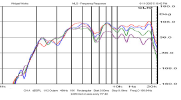
Per below graphs, the massive bump under 10k is bothersome

1715717458461.png

If I am reading the above graph correct, isn't the 4355 voltage drive optimal ?
I have tried 4344/4345 equivalent already and found it's upper treble too muted and mostly absent under 10k.
4344/4345 vs 4355 , will the 4355 equivalent be noticeably louder while also extending a bit more under 10k ?
 
Voltage drives ( into a static 8 ohm resistor ) rarely resemble the actual acoustic reality of the driver//network combo ( due to the fact that drivers themselves have their own highly reactive LC parts that interact << with the networks LCR parts >> in un-predictable ways ).

Believe it or not, you probably want to employ a network ( LCR ) layout that's more similar to the grey, or brown or blue voltage drives displayed ( assuming you want UHF response that goes down to 7 or 8K.

:)
 
So after reading quite a bit more on JBL networks
JBL 4343/L300/4350 have nearly identical HF sections
Per below graphs, the massive bump under 10k is bothersome

View attachment 3200979

If I am reading the above graph correct, isn't the 4355 voltage drive optimal ?
I have tried 4344/4345 equivalent already and found it's upper treble too muted and mostly absent under 10k.
4344/4345 vs 4355 , will the 4355 equivalent be noticeably louder while also extending a bit more under 10k ?
BION, the bump is intentional! The simple add-on N7000 and N8000 will not produce the bump.

The 2405/077 has a dip(s) in it's frequency response and the bump is created by the 1.0/1.5 cap combination. Look at the blue/green traces. The bump is intended to fill in this dip.
attachment.php
 
BION, the bump is intentional! The simple add-on N7000 and N8000 will not produce the bump.

The 2405/077 has a dip(s) in it's frequency response and the bump is created by the 1.0/1.5 cap combination. Look at the blue/green traces. The bump is intended to fill in this dip.
attachment.php

Todd, you're pic displays impedance traces ( not frequency response traces ) though the concept ( somewhat ) still holds true .

Here's one FR trace ( from Widget ) showing the polar response ( of a single unit ) taken every 15deg.

2405A_FR_.png
2405A_FR_.jpg

:)
 
Last edited:
Argh, looks like crossover design aren't exactly a cookie cutter
What makes it worse is variations in 2405 driver itself. I have 4 pairs, and each unit has inconsistent dips and peaks.

At least now I understand why a number of JBLs had 1uf and 1.5uf combination in HF. It actually does sounds least veiled with this but also the dreaded sizzle.
Wish the 2425/2307 could do upto 10k so that 2405 comes in after 10k only. 2405 doesn't sound at ease in that 8-10k region

I am going to try 2425 section from pass L300, and 3107 HF

The 0.16mH tapped inductor on 3107, equivalent circuits have it replaced with a regular 0.16mH inductor. Is it really that simple to replace tapped inductors ?

PS : Before JBLs I listened to music more and fiddle less. But the way JBL does dynamics it just makes the regular speakers sound like background music. Only if the JBLs had sorted FR linearity
 
Argh, looks like crossover design aren't exactly a cookie cutter

PS : Before JBLs I listened to music more and fiddle less. But the way JBL does dynamics it just makes the regular speakers sound like background music. Only if the JBLs had sorted FR linearity

Which is why I developed the Mermans (JBL 2241H 18"/JBL 2251J 9.5"/Modified ESS Great Heil AMT). ;)

In addition to the dynamics and slam, I have never heard speakers that can soundstage and image like these and anyone in the So Cal area (Orange County) is welcome to come by and hear them for themselves.

 
@Oyster150

Definitely try out this network cobbled together by Giskard&&Zilch.
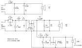
Giskards_Keeper 2405 CKT.jpg


The mid-horns LowPass ( L3 + C6 ) was grafted onto the original N200B circuit ( for the L200B ).
- an 8 ohm Lpad ( in the horn section ) works the same as the 16 ohm variety ( I've simmed both values and R2 + R3 simply dominate everything to their right ).

The HF ( or UHF here ) is a bog standard graft onto the mid range section.
- Where it taps off the midRange circuit is fairly unique ( called "cascading" ) , this tap-off works very well. ( it's highly recommended >> sonically ) .

Zilch built-up this circuit and measured all 3 parts ( individually and then together ) with the 2235H woofer working inside a JBL 4507 enclosure.
- The ( Woofer >> Horn ) crossover point is 900hz and Zilch has demonstrated that can provide a nice smooth response in that region ( if driver placements are matched to what Zilch used >> which might be important info that's hard to recover these days ).
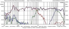
Zilch_Keeper-Network_flipped-MIDS_ 2405 4507.jpg

Now, this network was designed for the le85 ( not the 2425H ).
- The two driver types have slightly different responses ( and of course >> different impedances ).

Here's a comparison of the two drivers :

First a shot of 6 different le85 units measured by Zilch on the H91 ( 2307 );
- Amazing consistency!!


HL91 - 6 LE85s_60%_Zilch_.png

Here's a single 2425H ( of mine ) on a 2307;

JBL 2425H on 2307 without 2308 lense.png

Here's a comparison of the two ( one can see the le85 has more of a rising response than the 2425H, plus more extended LF
>> both factors effect the performance in the "Presence region ++ the crossover region with the woofer ) ;

Comparison of a 2425H to the le85  on 2307 horns without the 2308 lense.png


As a consequence of the HF difference between these two drivers ( ignoring the impedance differences ) substituting one for the other should really trigger some network design changes.

Here's one such "kick-at-the-can" ;

NOTE:
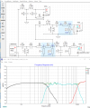
The resistors seen in light-blue are simply representing the 8-ohm variable LPads ( and dialed-down to some minus xx-db ).

Zilchs_modified Keeper-Network for 2425H + 2235H + 077 _.png


If I were you, I would try out Zilchs standard Keeper Network first.

If it doesn't hang together at 900hz then try my version ( but first try flipping the mid-horns polarity of the original "Keeper" ).

Also try out the Nelson Pass network ( again; play with the horn-circuits polarity >> especially since you'd be using the 2307 instead of the 2312 ).

Building-up one network or the other , will require that you have some form of methough I moved the HF to UHF crossover point ( midhorn to 077 tweeter ) to slightly above 10K.

Have Fun!! :)
 
Last edited:
@EarlK Thanks for the wealth of information. Didn't know 2425 can extend as much beyond 10k, can almost act as a tweeter!
Whats the value of R6 in your circuit ?

Last week I tried NP L300 crossover for mid and woofer

JBL3110a for woofer + 3106 for mid and tweeter : Bass sounds glorious. Violent dynamics, gets scary thunderous at times. Midrange is alright, its got good warmth but slight on darker side. Upper treble is outstanding, very surgical and pristine. But the 9k-12k region is wonky . It has several dead and bright spots.

NP L300 crossover for all three drivers (copied as is, without 6ohm 2425 series resistor) : Very bright. Woofer lost all its punch and sounded pretty weak. Midrange was ok
Because mine is a 141L cabinet with 2x 4.25" ports vs the larger L300 with 1x 4.25" port, bass response I think is vastly different between the two. If I block one of the ports on my unit, bass sounds boomy with 40-50hz emphasis

JBL 3110a for woofer + 3106 for midrange + NP L300 Midrange for tweeter : Sounds good. Midrange becomes even darker, but treble is now evenly spread out. No annoying peaks at least. But its also metallic at the same time. I have dial it down quite a bit via lpad

JBL 3110a for woofer + NP L300 Midrange (with 5ohm series resister to compensate for 8ohm driver) and tweeter : WTH, this shouldn't affect bass response at all but it does . There is a horrible boom/bloat in upper bass extending to lower midrange, maybe 200hz+

So far, the most promising has been 3110a for woofer+midrange and 3107 for tweeter. The caveat with this one is a weaker upper midrange

I have parts incoming for replicating 4344 MKII HF section. Charge couple FTW

Next I am going to try @EarlK 's circuit. I don't have most of those values.
 
Here; R6 doesn't electrically exist in the circuit, ( when ) as displayed >> that little icon shows open space ( and has no value entered ).

R6 ( when used ) controls the sharpness of the knee ( Q ) at the 10K HiPass.

:)
 
Last edited:
@EarlK On Zilchs network, lpad on MF is 16ohm. Can I use 8ohm in there with my 8ohm 2425? I have some 8ohms in stock
@Oyster150

Yes, I've used 8-ohm variable Lpads within all my circuit simulations.

Here's a ( very economical ) source for large value MPP in Oil motor-run capacitors.

Surplus Center > Motor-Run Capacitors

I'd suggest loading up on all sorts of values to make your breadboarding experiments more affordable.
- When necessary ( to obtain a value ), buy a dual value capacitor if a single isn't available ( and just use the appropriate section /// value of that "dually" cap ).

Also, I've tweaked the values in my version of the "Keeper" to better reflect the large value capacitors available from this outfit and really any outfit that sells motor-runs ( the changes made are imperceptible ).


Here are the tweaked values:

Zilchs_modified Keeper-Network for 2425H + 2235H + 077 _modB_.png


:)
 
Last edited:
JBL 3110a for woofer + NP L300 Midrange (with 5ohm series resister to compensate for 8ohm driver) and tweeter : WTH, this shouldn't affect bass response at all but it does . There is a horrible boom/bloat in upper bass extending to lower midrange, maybe 200hz+
@Oyster150

Reactions like you've stated are to be expected if one doesn't completely disconnect all unused legs from the various crossovers being tested.

Even without a driver connected the LCR components get connected in parallel with the "working" crossover ( typically ) causing very low impedance areas ( stressing the amplifier for more power ) and easily leading to an "under-damped" response ( just as you have described ).

When doing ( all your mix and matching ) you should still have only 3 individual parallel legs connected together at any one time
- ( IOW: 1x Woofer network leg, 1x Midrange leg + 1x HF//UHF leg ) . All the unused sections ( when using multiple networks ) need their entrance wires cut//disconnected .

:)
 
Last edited:
Thanks for explaining @EarlK . Thats is exactly what I did, didn't disconnect unused connections

Does that also mean I need to completely disconnect HF part of stock crossover (3106) while testing HF from other networks ?
 
Keep the DCRs of the coils ( L3, L4, L5 and L7 ) somewhere between 0.1 to 0.2 ohms .

L6 can be 2.6mH ( scavenged from your 3110a network >> it models just as well as the 2.7mH value ).
- If a 2.7mH coil is bought new > then keep it between 0.2 to 0.3 ohms ( you'll need to keep it as a solid laminate core to keep DCR low ).
- Personally I'd just try to re-use what you already have there.


Also, I'd recommend dismantling your 4 ( 3106 and 3110a ) networks and then use their parts ( just take good pics so that you can re-assemble them professionally and then sell them in the future >> if that ends up being a reality ).
- Once they are disassembled you can also more easily recreate the individual legs for your breadboarding experiments.

:)
 
Last edited:
Back
Top Bottom