• The move to the new server is done. There are some software and database maintenance updates in process. This has us passing the hat around to help out. We appreciate any donations. Seriously, even a dollar helps. The payment page may be found here - https://www.audiokarma.org/support.html

JBL 4333a/Sansui EC138

Raw Measurements

JBL 2425J on H92 (This is a near mint driver, originl Ti diaphragms. No lens and H92 horn)2425J.jpg

JBL 2420 on HL91
2420.jpg

I did various set of measurements, dip position changes here and there but it is always there.
Did I get a bad set of drivers or can the MIC possibly have this inherent dip?
I am inclining towards drivers, since this dip is audible
 
You'll need to create some additional confidence that your measurement mic is working properly by measuring other drivers ( that you know have linear HF response ).

The fact that the center frequency of each notch seems tied to the length of the horns ( H91 vs H92 ) is suspicious to me ( as if the notch is created by a reflection of some sort ).
- Hopefully you're using a boom with a mic stand to extend the mic away from reflective surfaces ( and not just holding it ).

A properly working le85/2420 ( 100% charged magnet ) should have a rising response on the H91 ( as demonstrated by Zilch ).

:)
 
You'll need to create some additional confidence that your measurement mic is working properly by measuring other drivers ( that you know have linear HF response ).

The fact that the center frequency of each notch seems tied to the length of the horns ( H91 vs H92 ) is suspicious to me ( as if the notch is created by a reflection of some sort ).
- Hopefully you're using a boom with a mic stand to extend the mic away from reflective surfaces ( and not just holding it ).

A properly working le85/2420 ( 100% charged magnet ) should have a rising response on the H91 ( as demonstrated by Zilch ).

:)
That would depend on if Zilch used the diamond or tangential 2420s. But, if you look carefully at Zilch's graphic, you still see this dip, just not so severe and it is masked by the rising response.

Again, do we know which diaphragms Zilch used?

2420 on a 2307. I don't know which 2420, but the dip is still there.
attachment.php

JBL 4345. Note the roughness in that area. Also note the dip at ~1.7KHz.
attachment.php

LE85 on H91. So take it for what it's worth and recognize this is why I moved on to the Heil.
attachment.php
 
Todd,

The graph you just displayed was generated by RobH3606 from HERE!.

( Resized below for a smoother presentation );
RobH 2425-6 aquaplas +2307.png

Rob said:
Hello Widget

That is a 2425 with an Aquaplased 2426 Ti diaphram. It was mounted in my 4344 using a 2307 horn with no HF compensation and no crossover in place. That is with the lense removed.

Rob


Again, do we know which diaphragms Zilch used?

I'm pretty confident that the graph I posted ( of the full system response for the "Keeper" ) was for an intact le85 with original diaphragm having the tangential surround.

To the best of my knowledge, Zilch never cracked open any of his le85s ( & he had stated that they mostly all had the wax seals intact ) plus he usually tested with unit serial # 22222 according to most of the pics I have from him.

:)
 
Last edited:
I'm pretty confident that the graph I posted ( of the full system response for the "Keeper" ) was for an intact le85 with original diaphragm having the tangential surround.

To the best of my knowledge, Zilch never cracked open any of his le85s ( & he had stated that they mostly all had the wax seals intact ) plus he usually tested with unit serial # 22222 according to most of the pics I have from him.

:)
IIRC, they were both original depending on the year the driver was made with the diamond pattern being the later model. The 2425 was similar to the later pattern, but made of titanium.

Also, do we know what distance each measurement was taken at?

Edit: Come to think of it, I have an aluminum diamond surround that I pulled out of the 2420 in my center channel when I actually did find an original tangential surround on ebay that had been missed-advertised as a 2425 diaphragm because it was in a 2425 box. I figured someone blew a diaphragm, changed the pair, and put the good one in the new box for safe keeping.

IIRC, I got it for the unheard of price of $65 because 2425 diaphragms are not in high demand. But original tangential diaphragms are made of unobtanium and can fetch high dollars if unearthed. When the seller realized his mistake, he asked me if I wanted to cancel. No......
 
Last edited:
Latest

Having tried numerous ways to get a resonable crossover response and not being content with any, took a new direction
Since I had 2420 and HL92 lying around, DIY'd a L300 clone

WhatsApp Image 2026-03-31 at 10.33.55 PM.jpeg

This is with 2216nd woofer and not the 2235h
2235H, while I absolutely love it's bass dynamics, it sounded so dead in midrange
Especially after using 2216ND, 2235H really is dull post 500-600hz
2216nd and 2420 just melt into each other and basically can't tell the crossover region, it's that good.

Where 2216nd can't match 2235h is the sub bass region. Sub bass is kinda extinct in the L300 enclosure and Nelson Pass L300 crossover

Was reading into some threads over at LH, where some folks tried 2216nd with L300

Question to @EarlK
Will this be a better implementation for 2216nd + 2420 / HL92 ? I see that the rising response of 2216nd is subdued in this one (wondering if it may end up sounded dead like the 2235h in midrange)

1775396086739.png

There's also this one:
1775396290627.png
 
@EarlK
 
@EarlK

Thanks @Oyster150 !

You'd be well ahead if you simply asked RobH3606 ( from one of those threads seen over at LHF ) what he thinks about the balance between Bass and Midrange dynamics ( for the 2216nd ) with his referenced Woofer circuit for his passive M2's .

Later today, I'll post a compromise woofer circuit for you to try out ( it'll mostly uses your existing passive parts ).

:)
 
@Oyster150

Here's a pic showing a modified lowpass for your existing Nelson Pass network.

What it does is adds another smaller inductor ( 0.68mH ) to the lowpass section and re-uses your big 22uF caps.

FYI, Just about all of JBL's newer woofers ( for the last 30 years ) have a "rising response" ( typically ) dictating the use of a 3-pole low-pass to flatten them out.

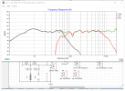
Green trace = 2216nd ( on the modified Low-Pass )
Red trace = 2235H ( on the Nelson Pass Low-Pass )


JBL L300 lowpass with 2216nd matching 2235H NelsonPass 2026-04-06.png

The purpose of this exercise is to get the lowpass roll-off near crossover ( for the 2216nd ) to match the intended LP roll-off of the 2235H ( as produced by the Nelson Pass network ).


One can see my mod produces a near perfect match ( between 600hz to 1K ) with the small modification ( to deal with the rising response of the 2216nd ).

Ignore the differences below 300hz >> they are attributable to the impedance files I used and give a false impression of the bass output.

Listen to this modified lowpass for at least a week to see if the balance between bass and mids is more to your liking ( or not ).

FYI, by not modifying the Nelson Pass low-pass ( and simply lashing up a 2216nd onto it ), the following pic shows the resulting lazy low-pass.

Green trace = 2216nd ( on the un-modified Nelson Pass Low-Pass )
Purple trace = 2216nd ( on the modified Nelson Pass Low-Pass )


JBL L300 lowpass modded vs NelsonPass, both with 2216nd_2026-04-06.png

2216nd and 2420 just melt into each other and basically can't tell the crossover region, it's that good.

That "lazy" ( @ 6db/octave ) roll-off that you are currently listening to, might be the reason for the "seamless" transition from Woofer to Horn that you've mentioned.

This is something you'll need to listen for ( after the mods are made ) to see if this transition suffers ( what with the steeper x-over slope produced by the Pass network ).

PS; You may need to eventually add another coil ( inline with your existing 2.2 mH coil ) to get that first coil's value closer to what RobH3606 did ( but I wouldn't do that quite yet until this exercise is completed ).


:)
 
Last edited:
Thanks @EarlK
I do not have an account at LH. LH also doesn't allow new registrations

About this:
1775656207427.png

I tried a 2.7mh + 1.2mh with a 33uf cap and no resister. It did provide a beefier bass vs nelsen pass values
But i'd like a bit more

Will 2.2 + .68 with 44uf help to get low end extension and volume ?
I do not have a .68mh with me right now. Therefore asking before ordering one
 
@Oyster150

I'll post some suggestions and thoughts in about an hour.

In the meantime, how's this new transition ( from Woofer to Horn ) compare to what you started with ( after subbing-in the 2216nd ) ??

:)
 
@Oyster150

If I understood your words correctly ( from post #93 ) you've now implemented a 3-pole low-pass ( consisting of these 2.7mH, 33uF, 1.2mH components ).

The following pic shows the predicted responses of 2 similar combos.

The Red Trace : represents a "control-curve" ( as produced by a 2235H woofer being filtered through the Nelson Pass low-pass ).
It's most relevant above say, 500hz.


The Green Trace ; represents the 2216nd ( with your just mentioned passives > but slightly modified ) filtered through your 3-pole low-pass.
I've added a 1.5R resistor to modify "the knee" of the turn-over ( because without it, that knee is under-damped > giving a bit of midrange boost just before rolling off ).

FYI, the values that you've used ( with the added resistor ) nicely approximate the intended roll-off of the Nelson Pass woofer circuit ( low-pass ) > so that's a big Win! ;)

You can refer to your current arrangement ( as now implemented ) as @ 1/2 BSC ( Baffle Step Compensation ). Midrange reduction is @ 2-2.5db compared to the bass frequencies .

The Grey Trace : This trace represents a 2216nd getting a full 5db of BSC where the midrange has been attenuated by 5 db when compared to the bass output around 100hz and lower.

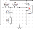
This trace is achievable by wiring up a 3-pole low-pass consisting of a ( 3.9mH coil, followed by a 30uF cap going to ground through a 0.33R resistor and then another 0.68mH series coil ). See the following pic for some clarification.

JBL L300, (2x) 3-pole lowpass for 2216nd_full-BSC+half-BSC_2026-04-08.png


The 3.9mH coil can be created by wiring your already existing coils in series ( 2.7mH + 1.2mH = 3.9mH ).

Keep them a few inches ( say 3 ) apart to minimize any mutual coupling///interaction ( which might increase or decrease the overall inductance > depending on coil orientations ).

:)
 
Last edited:
Going to implement this and report back
Thanks @EarlK

BTW, with this "a 3-pole low-pass ( consisting of these 2.7mH, 33uF, 1.2mH components )" , midrange was tiny bit overpowering, lowered down via lpad
I think the grey trace is what should give better balance
 
Hah, whatever happened to my previous post :confused:
Anyways, @EarlK , I implemented your crossover and it's indeed quite an improved one over previous iterations
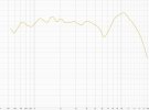
JBL 2216nd + LE85 + 2405 in L300 cabinet
Top one is Earlk's crossover (green : LE85 and 2405 in same polarity, purple: 2405 inverted)
Bottom one is Original L300 crossover

Shashi's L300 Mods.jpg
See how 5k+ region is much better behaved
Can we also make the 1k-3k region any flatter?
 
Anyways, @EarlK , I implemented your crossover (???) and it's indeed quite an improved one over previous iterations
JBL 2216nd + LE85 + 2405 in L300 cabinet
Top one is Earlk's crossover (green : LE85 and 2405 in same polarity, purple: 2405 inverted)
Bottom one is Original L300 crossover

@Oyster150,

I'm confused by your wording here.

As far as I can remember, I've only made some suggestions for a custom "low-pass circuit" for your 2216nd woofer <<>> not a full crossover.

Enlighten me ( please ) as to just exactly which HiPass, LowPass and UHF sections you have wired together to get the results shown above ( post# 97 )??

I have no doubt that the 1K to 3K bump can be removed >> but I need to know what exactly is your starting point ( schematic wise ) before making any suggestions.

:)
 
@EarlK
My bad, I have so many iterations that I had to see what was running :biggrin:

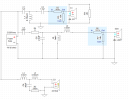
Here you go:
Basically, your LF circuit + nelsen MF circuit + original L300 HF circuit

1786262044719.png
 
@Oyster150

Thanks!

So; You'll need to first determine the cause of this 1-3K "bump".

To that end; disconnect the woofer and then take an REW measurement of the horn ( with lens in-place ) from 1/2 a meter out ( in line with the horn-throat and maybe 10deg off axis ).

Post the results here.

If it's not "baked-into" the horn//driver response that you just made > then it means that there's too much overlap between the woofer and horn sections of the crossover >> which means adjusting either the values in the low-pass or the hi-pass sections ( or both ) to achieve a smoother transition.
- For instance ; reducing the 22uf cap ( in the Nelson Pass hipass ) down to 10uF, should reduce some of the overlap ( if that's the actual cause of the problem ).

:)
 
Last edited:
Back
Top Bottom