• The move to the new server is done. There are some software and database maintenance updates in process. This has us passing the hat around to help out. We appreciate any donations. Seriously, even a dollar helps. The payment page may be found here - https://www.audiokarma.org/support.html

Kenwood KR-3030 DC offset

AudioGMan

Well-Known Member
There isn’t much information on this model online. Does anyone know if the DC offset is adjustable on Kenwood KR-3030 and if so which pots are they? I measured it and got 49.7mV(left) and 55.0(right). I would appreciate any input.
 
Register to hide this ad
Some information suggests that the 3030 and 3010 are the same, and there’s more data available for the KR-3010.
 
It appears that the "3030" was a Euro version of the KR-3010, just as @A400 commented.

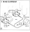
It also appears that idle current (bias) is adjustable via R109/R110 in the L and R channels, respectively. The specification is for a 20mV indication across R119/121 (L channel) and R120/122 (R channel) which would represent 30mA given the pair of those 0.33Ω resistors in series.

KR-3010 Bias Adjustments.jpg
 
It appears that the "3030" was a Euro version of the KR-3010, just as @A400 commented.

It also appears that idle current (bias) is adjustable via R109/R110 in the L and R channels, respectively. The specification is for a 20mV indication across R119/121 (L channel) and R120/122 (R channel) which would represent 30mA given the pair of those 0.33Ω resistors in series.
T
It appears that the "3030" was a Euro version of the KR-3010, just as @A400 commented.

It also appears that idle current (bias) is adjustable via R109/R110 in the L and R channels, respectively. The specification is for a 20mV indication across R119/121 (L channel) and R120/122 (R channel) which would represent 30mA given the pair of those 0.33Ω resistors in series.

View attachment 3486872
T
Use mini-grabbers if at all possible:

View attachment 3486886
Thank you so much for that. I’m kind of confused though. If the DC offset that I measured at the speaker posts is too high does that automatically mean the bias will also be out of spec? Do I initially have to adjust the bias first and that will bring the DC offset down?
 
Last edited:
A @kwade mentioned, there seems to be no adjustment for offset. Unless it is insanely high, it is probably not a problem. I have a slightly older KR-6400 which uses a similar design providing adjustments for bias but not offset. If you are ambitious, the circuit could be altered to introduce some adjustment at the positions of either R87 or R91 (L channel) and R99 or R92 in the R channel. A 5.6KΩ resistor paralleled by a 5K trimpot might be a start.
 
A @kwade mentioned, there seems to be no adjustment for offset. Unless it is insanely high, it is probably not a problem. I have a slightly older KR-6400 which uses a similar design providing adjustments for bias but not offset. If you are ambitious, the circuit could be altered to introduce some adjustment at the positions of either R87 or R91 (L channel) and R99 or R92 in the R channel. A 5.6KΩ resistor paralleled by a 5K trimpot might be a start
 
Thank you so much for that. I’m kind of confused though. If the DC offset that I measured at the speaker posts is too high does that automatically mean the bias will also be out of spec? Do I initially have to adjust the bias first and that will bring the DC offset down?
Bias is idle current, and has very little affect on DC offset. DC offset is function of input pair (Q17 Q19 left channel, Q18 Q20 right channel) ) and input and feed back resistors. Higher HFE (current gain) of input transistors will reduce off set a little bit, but not much. Decreasing R81 (input resistor) from 100k to 56K should bring it down if the input transistors are matched. Messing with feedback resistor will give you other problems... Rather than changing resistor, try paralleling it with a 120K resistor, which gets 55K. (tack it across the two ends of the existing resistor) IMHO circuit appears to be working as expected. Lowering the resistance will slightly raise the low frequency limit. Changing C75 and C76 to 2.2uf brings it back to where it was (but it probably won't be audible...) Bonus is you could put in film type, if it will fit. My 2 nickels.
 
A @kwade mentioned, there seems to be no adjustment for offset. Unless it is insanely high, it is probably not a problem. I have a slightly older KR-6400 which uses a similar design providing adjustments for bias but not offset. If you are ambitious, the circuit could be altered to introduce some adjustment at the positions of either R87 or R91 (L channel) and R99 or R92 in the R channel. A 5.6KΩ resistor paralleled by a 5K trimpot might be a start
 
Back
Top Bottom