

You are using an out of date browser. It may not display this or other websites correctly.
You should upgrade or use an alternative browser.
You should upgrade or use an alternative browser.
LED backlighting 9090DB
- Thread starter DougBrewster
- Start date
Register to hide this ad

Tinnkindling
OLD SCHOOL
Excellent. Can you post more information on the mod. How about a part number and source for the bulbs? Maybe a picture of the installation of the bulbs...

wondering the details in accessing the dial lights on these, my 8080DB has a broken solder joint. Tap the dial and it come right back on..
more pics
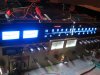
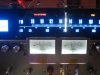
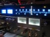
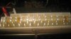
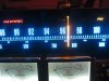
here's another pic; they don't show the richness of the colours properly because I'm a beginner with cameras. I'll certainly post info on the changes I've made and sourcing of the LEDs. For the moment let me say there are 40 LEDs in the main scale, 2 in each power meter and another 16 between the signal/tune meters. The function lamps above the main tuning scale have another 19 between them. The main scale, power meters and signal/tune meters are powered by using the volt drop(waste heat) in the 12v tuner power supply dropper resistors so heat release into the case is considerably reduced. The function lamps are powered by their original 6.2v ac supply, rectified and stabilised at 4V DC. It's 11:30pm here so more tomorrow.
FYI..
here's another pic; they don't show the richness of the colours properly because I'm a beginner with cameras. I'll certainly post info on the changes I've made and sourcing of the LEDs. For the moment let me say there are 40 LEDs in the main scale, 2 in each power meter and another 16 between the signal/tune meters. The function lamps above the main tuning scale have another 19 between them. The main scale, power meters and signal/tune meters are powered by using the volt drop(waste heat) in the 12v tuner power supply dropper resistors so heat release into the case is considerably reduced. The function lamps are powered by their original 6.2v ac supply, rectified and stabilised at 4V DC. It's 11:30pm here so more tomorrow.
FYI..
Attachments

swamppirate
Lunatic Member
Nice job.

river25
Super Member
Nice!
I too have done the LED upgrade to my 9090, except I used blue LEDs for the power meters. I thought it would look good but not as good as I hoped so I'll be doing some more work on this unit in the next few weeks and I will change the power meter LEDS to green or white (I'll experiment).
I will load some pics this evening when I get home, assuming I get the time.
In regards to what LEDs to use, I use the standard 5mm super-bright LEDs for the dail backlight, a 3mm super bright orange LED for the needle light.
The power supply for the LEDs is tapped from the existing lamp AC voltage. I mount a small full-wave bridge rectifier and filter capacitor, plus a current limit resistor on a small veroboard, and I mount this within the amp. From there I connect the LEDs and it's all fine.
This mod leaves the existing AC in place which allows me to use a mix of LEDs and bulbs, and also a 5 minute job to revert back to full AC, if required.
I LED most of my old receivers to avoid hassling around and trying to get lamps, and when done properly the LED looks as good as lamps and will last forever.
The nicest conversion I have done was to an old Realistic STA-870, which came up really nice and looks fantastic. I must put a few pics of it up also.
I too have done the LED upgrade to my 9090, except I used blue LEDs for the power meters. I thought it would look good but not as good as I hoped so I'll be doing some more work on this unit in the next few weeks and I will change the power meter LEDS to green or white (I'll experiment).
I will load some pics this evening when I get home, assuming I get the time.
In regards to what LEDs to use, I use the standard 5mm super-bright LEDs for the dail backlight, a 3mm super bright orange LED for the needle light.
The power supply for the LEDs is tapped from the existing lamp AC voltage. I mount a small full-wave bridge rectifier and filter capacitor, plus a current limit resistor on a small veroboard, and I mount this within the amp. From there I connect the LEDs and it's all fine.
This mod leaves the existing AC in place which allows me to use a mix of LEDs and bulbs, and also a 5 minute job to revert back to full AC, if required.
I LED most of my old receivers to avoid hassling around and trying to get lamps, and when done properly the LED looks as good as lamps and will last forever.
The nicest conversion I have done was to an old Realistic STA-870, which came up really nice and looks fantastic. I must put a few pics of it up also.

I've found that cameras don't capture how nice LED lighting may look in person. I have done a few lighting mods and whenever I took pictures they never looked right. (Usually too bright even if I lessened the exposure or ISO). It always looks so different on camera, but in person it just probably looks a bit clearer and maybe slightly brighter than the original incandescent lighting.
Either way, congrats on the upgrade. It will last infinitely longer than the originals, much less heat, and probably better lighting too. It seems like you used more LEDs to keep the lighting even, which can be a problem with LEDs. It looks good. looking forward to your info about what you used.
Either way, congrats on the upgrade. It will last infinitely longer than the originals, much less heat, and probably better lighting too. It seems like you used more LEDs to keep the lighting even, which can be a problem with LEDs. It looks good. looking forward to your info about what you used.

here's another pic; they don't show the richness of the colours properly because I'm a beginner with cameras. I'll certainly post info on the changes I've made and sourcing of the LEDs. For the moment let me say there are 40 LEDs in the main scale, 2 in each power meter and another 16 between the signal/tune meters. The function lamps above the main tuning scale have another 19 between them. The main scale, power meters and signal/tune meters are powered by using the volt drop(waste heat) in the 12v tuner power supply dropper resistors so heat release into the case is considerably reduced. The function lamps are powered by their original 6.2v ac supply, rectified and stabilised at 4V DC. It's 11:30pm here so more tomorrow.
FYI..
Nicely done Doug - and a very elegant and thoughtful solution to the tuner PSU dropper resistor situation to boot. :thmbsp:
wondering the details in accessing the dial lights on these, my 8080DB has a broken solder joint. Tap the dial and it come right back on..
With the top cover removed, look down onto the front chassis rail and you'll see two holes, one at each end of the main tuning scale, through which you'll see a pair of cross head screws. Take these two screws out (don't just loosen them because they may jam the lamphouse and break off the lugs) and roll the whitish plastic lamphouse backwards from the topside so that the bottom half can clear the antennae connection to the tuner. Once the top edge of the lamphouse is clear of the chassis it lifts out to give access to the lamps. There are usually cracked solder joints between the lampholders and the pcb on the back of the lamphouse which need to be reflowed or better, completely resoldered.
Further info as promised
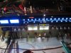
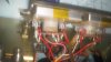
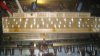
Here are some more pictures. Let me briefly explain the LED arrangement; the tuner main scale has 40 Piranha Ultra Bright 20mA LEDs. They are arranged in 10 groups of 4 LEDS in series, each group having it's own series resistor of 150ohms. The 10 groups are parallel connected so the current draw/carrying capacity of the whole matrix is 10 x rated current = 200ma with a volt drop across the matrix of around 14V (including 2.4V across the resistors). However the actual current draw from the tuner 12V supply is 160mA in FM stereo and about 170mA in AM so I'm running the LEDs at 75-85% rating (with slightly reduced volt drop).
The positioning of the LEDs looks a little odd; this because the angle of illumination with these things is quite narrow and after several iterations with various LED types I've found that to avoid less bright areas there needs to be a LED behind each numeral/letter group. There are 34 numeral/letter groupings so you could use 9 groups of LEDs (total 36) instead of 10 but I prefer the reduced current loading. The LEDs "left over" are simply placed in black spots.
In the original design the 53V DC supply to the tuner and auxiliaries is dropped in R01/R02 on F-2619 to around 19v (the drawing says 14V but it's not) meaning that there's 34V being dropped across R01/R02 as waste heat - about 5.5 watts worth.
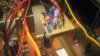
I've connected the 53V to the matrix positive then taken the matrix negative to the power meters where there are 2 x 100mA 8mm Straw Hat Ultra Brights in each meter; these are mounted such that their noses just poke into the original 5mm holes in the back of the meter. I've used cut-off diode stalks soldered into the meter PCBs to hold them in place. They each have a series connected 47 ohm resistor. The LEDs in each meter are in parallel (80mA x 2 =160mA) so again under-rated. The two meter assemblies are connected in series giving a further volt drop of about 7v across each meter.
The output continues on to the signal/tune meters where I've again used Piranha Ultra Brights as in the main tuner scale only this time there are only 16 of them in 8 parallel groups each having 2 LEDs in series (and a 100ohm resistor) giving a volt drop of about 8.4V across the assembly.
All these volt drops leave about 16-17V for the tuner PSU which means it's working less hard also but with enough voltage headroom for main supply dips.
Apologies in advance for picture quality.
The Piranha Ultra Brights are available in the US from Lighthouse Leds and in UK from Microminiatures. The 8mm Straw Hat Ultra Brights are also available from Lighthouse Leds and various fleabay sites.
More on the function lamps and FM stereo indicator later; it was rather tricky...
Here are some more pictures. Let me briefly explain the LED arrangement; the tuner main scale has 40 Piranha Ultra Bright 20mA LEDs. They are arranged in 10 groups of 4 LEDS in series, each group having it's own series resistor of 150ohms. The 10 groups are parallel connected so the current draw/carrying capacity of the whole matrix is 10 x rated current = 200ma with a volt drop across the matrix of around 14V (including 2.4V across the resistors). However the actual current draw from the tuner 12V supply is 160mA in FM stereo and about 170mA in AM so I'm running the LEDs at 75-85% rating (with slightly reduced volt drop).
The positioning of the LEDs looks a little odd; this because the angle of illumination with these things is quite narrow and after several iterations with various LED types I've found that to avoid less bright areas there needs to be a LED behind each numeral/letter group. There are 34 numeral/letter groupings so you could use 9 groups of LEDs (total 36) instead of 10 but I prefer the reduced current loading. The LEDs "left over" are simply placed in black spots.
In the original design the 53V DC supply to the tuner and auxiliaries is dropped in R01/R02 on F-2619 to around 19v (the drawing says 14V but it's not) meaning that there's 34V being dropped across R01/R02 as waste heat - about 5.5 watts worth.
I've connected the 53V to the matrix positive then taken the matrix negative to the power meters where there are 2 x 100mA 8mm Straw Hat Ultra Brights in each meter; these are mounted such that their noses just poke into the original 5mm holes in the back of the meter. I've used cut-off diode stalks soldered into the meter PCBs to hold them in place. They each have a series connected 47 ohm resistor. The LEDs in each meter are in parallel (80mA x 2 =160mA) so again under-rated. The two meter assemblies are connected in series giving a further volt drop of about 7v across each meter.
The output continues on to the signal/tune meters where I've again used Piranha Ultra Brights as in the main tuner scale only this time there are only 16 of them in 8 parallel groups each having 2 LEDs in series (and a 100ohm resistor) giving a volt drop of about 8.4V across the assembly.
All these volt drops leave about 16-17V for the tuner PSU which means it's working less hard also but with enough voltage headroom for main supply dips.
Apologies in advance for picture quality.
The Piranha Ultra Brights are available in the US from Lighthouse Leds and in UK from Microminiatures. The 8mm Straw Hat Ultra Brights are also available from Lighthouse Leds and various fleabay sites.
More on the function lamps and FM stereo indicator later; it was rather tricky...
Attachments
Thanks Doug, that helped a lot, appreciate it! :thmbsp:
Last chapter; function lamps
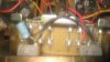
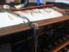
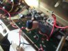
The function lamps are all 5mm Flat Top 20mA LEDs (from Lighthouse Leds in the US and Microminiatures in the UK though they're very widely available all over eb_y. I'm running them from a 4V (DC of course) supply derived from the original lighting supply of 6.2Vac via F3 which has been down-rated to 500mA quick-blow; I'll reduce it further when I find some lighter fuses because it it only pulls about 140mA max. I've pictured the rectifier/regulator (LM317T from anywhere) mounted to a handy screwhole on the chassis above the function selector board F2653. The supply is very stable and has ripple of less than 1mV - good for LED life.
In the image of 2 LEDs (for AM) next to an original lamp for comparison, I needed to file about 1/32" off the LED flanges on one side so they would sit neatly together on the 1/10" pitch stripboard on which they're mounted. Anywhere you see LEDs immediately adjacent to each other this was necessary.
The FM Stereo lamp was difficult to get working because of 50Hz noise from the stereo decoder pin 9 which drives the base of TR09 for the original indicator lamp. Noise didn't matter in the original scheme but it does with LEDs and the only way I've been able to get the noise down so far has to use TR09 to drive the coli of a sub-miniature relay (Omron G6J-2P-Y 5VDC) to give complete isolation of noise. The 390uF capacitor across the coil pumps the volts up to hold the relay in. Hopefully, one of the experts reading this will have a more elegant solution to this noise contamination issue, because I can't figure one out and I'd prefer to not have a relay in the system.
All the LEDs have an appropriately sized resistor to run them at 75% of their full rated current for max life.
I've been pleasantly surprised at the positive nature of the comments in response to this thread, expecting that some folks would not like the idea (and they're welcome to that opinion of course).
\any questions, please ask...
The function lamps are all 5mm Flat Top 20mA LEDs (from Lighthouse Leds in the US and Microminiatures in the UK though they're very widely available all over eb_y. I'm running them from a 4V (DC of course) supply derived from the original lighting supply of 6.2Vac via F3 which has been down-rated to 500mA quick-blow; I'll reduce it further when I find some lighter fuses because it it only pulls about 140mA max. I've pictured the rectifier/regulator (LM317T from anywhere) mounted to a handy screwhole on the chassis above the function selector board F2653. The supply is very stable and has ripple of less than 1mV - good for LED life.
In the image of 2 LEDs (for AM) next to an original lamp for comparison, I needed to file about 1/32" off the LED flanges on one side so they would sit neatly together on the 1/10" pitch stripboard on which they're mounted. Anywhere you see LEDs immediately adjacent to each other this was necessary.
The FM Stereo lamp was difficult to get working because of 50Hz noise from the stereo decoder pin 9 which drives the base of TR09 for the original indicator lamp. Noise didn't matter in the original scheme but it does with LEDs and the only way I've been able to get the noise down so far has to use TR09 to drive the coli of a sub-miniature relay (Omron G6J-2P-Y 5VDC) to give complete isolation of noise. The 390uF capacitor across the coil pumps the volts up to hold the relay in. Hopefully, one of the experts reading this will have a more elegant solution to this noise contamination issue, because I can't figure one out and I'd prefer to not have a relay in the system.
All the LEDs have an appropriately sized resistor to run them at 75% of their full rated current for max life.
I've been pleasantly surprised at the positive nature of the comments in response to this thread, expecting that some folks would not like the idea (and they're welcome to that opinion of course).
\any questions, please ask...
Attachments



river25
Super Member
I think it's a great conversion, and looks great all lit up, however I don't know why you need so many LEDs.
For the radio backlight, if you run two thicker tinned wires across the top and bottom of the bulb holders, you can attach LEDs between the two rails. You will only need 6-8 super bright 5mm LEDs to give a bright consistent display. This is assuming you run them off DC. If you keep the AC, you can mount a pair in series, but back-to back, this way one LED will be illuminated all the time, depending on the phase. You need a current limit resistor, depending on the voltage, and while it will only be 1 LED bright, it won't flicker.
With the function LEDs, the same applies, where it is easier to keep the AC voltage and run two small 3mm super bright LEDs back-to-back. Same for the tuning meters.
The dial needle is another 3mm super bright LED.
The power gauges I used a pair of super bright (5mm) per gauge. I fitted them in where the old lamps used to go. I run these off a small DC supply board, similar to what you have done to get DC.
I don't have any noise from my LED conversion, but it's not a full conversion and it runs a lot less LEDs than your set up.
For the radio backlight, if you run two thicker tinned wires across the top and bottom of the bulb holders, you can attach LEDs between the two rails. You will only need 6-8 super bright 5mm LEDs to give a bright consistent display. This is assuming you run them off DC. If you keep the AC, you can mount a pair in series, but back-to back, this way one LED will be illuminated all the time, depending on the phase. You need a current limit resistor, depending on the voltage, and while it will only be 1 LED bright, it won't flicker.
With the function LEDs, the same applies, where it is easier to keep the AC voltage and run two small 3mm super bright LEDs back-to-back. Same for the tuning meters.
The dial needle is another 3mm super bright LED.
The power gauges I used a pair of super bright (5mm) per gauge. I fitted them in where the old lamps used to go. I run these off a small DC supply board, similar to what you have done to get DC.
I don't have any noise from my LED conversion, but it's not a full conversion and it runs a lot less LEDs than your set up.
Why lots of LEDs
"think it's a great conversion, and looks great all lit up, however I don't know why you need so many LEDs"
Part of the objective was to usefully use the waste power across R01/R02 in the tuner power supply; this meant I needed to handle as much as 175mA through the main scale/power meters and signal/tune LEDs whilst dropping around 34V across them and have a modest safety margin. The other reason was to get completely even lighting with no dull spots.
I like your idea of running LEDs back to back but LEDs are picky about ac including ripple; how much life are you getting or is it too early to tell? I've had several failures due to (I think) ripple which now appears to be resolved after several iterations...
"think it's a great conversion, and looks great all lit up, however I don't know why you need so many LEDs"
Part of the objective was to usefully use the waste power across R01/R02 in the tuner power supply; this meant I needed to handle as much as 175mA through the main scale/power meters and signal/tune LEDs whilst dropping around 34V across them and have a modest safety margin. The other reason was to get completely even lighting with no dull spots.
I like your idea of running LEDs back to back but LEDs are picky about ac including ripple; how much life are you getting or is it too early to tell? I've had several failures due to (I think) ripple which now appears to be resolved after several iterations...

CharlieBee
Super Member
Thanks for the great article on LED lighting a 9090.
After seeing all that is involved you have convinced me to stick with those original dreaded fuse style incandescent bulbs as long as the federal government lets us keep buying them.
Charlie
After seeing all that is involved you have convinced me to stick with those original dreaded fuse style incandescent bulbs as long as the federal government lets us keep buying them.
Charlie

Joao Pedro
New Member
I saw recently that people are making these led´s conversion and most of them are really good and they are so cool looking, maybe in future a can do the same in my Sony str-4800 receiver


