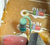
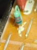
I believe they are located on the APS thin strip circuit boards.I also cannot find C347-C350 on the reference amp.


I believe they are located on the APS thin strip circuit boards.I also cannot find C347-C350 on the reference amp.

Not according to the TSB. I am looking at my M-80 serial # 11454 as a reference, but this might not be a good idea. The TSB is for serial #'s below 02401, so is it possible that there is a different TSB for serial #'s above 02401 or that the changes were done in the factory and are different than what is in the TSB?I believe they are located on the APS thin strip circuit boards.

Yes, on one amp I've seen that actually had these caps, they were soldered to the top (foil side) of the APS circuit board. They were presumably added at the factory, being the light green caps, polyester, that Yamaha used in other locations for these amps. But they did not add the 33 ohm resistors on that particular amp.I believe they are located on the APS thin strip circuit boards.
Yes... In the M-85 schematic they are documented R241 & R243..I am curious, does anyone have an M-80 with the resistors tied to TR 117 and 123? Are they 47 Ohms?
Thanks, I see that. So, for M-80s from SN above 2401 to some point before or at the M-85 there is a different fix that was implemented. I assume an M-85 does not have a resistor tied around any TR's legs. Were all the amps above SN 2401 fixed in the factory, so no TSB? Are the amps above SN 2401 identical to the M-85?Yes... In the M-85 schematic they are documented R241 & R243..
Don't assume.. Because they are still tied to the base legs in the M-85.I assume an M-85 does not have a resistor tied around any TR's legs.
M-85 is and M-80 with all the service bulletins complied with. They make identical power...At almost 300wpc @ 1Khz before clipping into and 8Ω load.( 297 wpc )Are the amps above SN 2401 identical to the M-85?

Really! Ok, yes, should not assume. "It makes an ....out of u and me."Don't assume.. Because they are still tied to the base legs in the M-85.
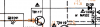
The most accurate schematic for the M-80/85 is the M-85 SM.. But it still has some of the same errors in the schematic as in the M-80 schematic.I can reference the M-85 SM.
Should be unless you found another error.If they are still tying in R241 at the base of TR117, then D129 would actually be connected on the other side of R241, yes?
View attachment 2429871
The most accurate schematic for the M-80/85 is the M-85 SM.. But it still has some of the same errors in the schematic as in the M-80 schematic.
Yes, on one amp I've seen that actually had these caps, they were soldered to the top (foil side) of the APS circuit board. They were presumably added at the factory, being the light green caps, polyester, that Yamaha used in other locations for these amps. But they did not add the 33 ohm resistors on that particular amp.
If I recall correctly, to add the 33 ohm resistors and 0.01uF caps specified in the TSB, you must remove the short jumper wires that connect the supplies to the driver transistors, and replace them with the parallel combination of the resistor and cap. You can do this in various ways. On one amp, I soldered the resistor to the cap, then soldered the assembly in place of the original jumper wire. On another amp, I installed the cap in place of the jumper, then added the resistor on top (foil side) of the APS board, thinking that I could replace the resistor, if necessary, without removing the APS board.
Truthfully all the M-80's I have worked with in the past ( at least 10 or 12 ) were higher S/N's and the service bulletins were already complied with..ie. factory installed.But an amp with SN below 2401 will be different with different parts in different places than amps above 2400.
Probably . Accurate..Have you seen brutals marked up schematic, is it accurate?
 I have nothing to compare it to..
Are these amps SN below 2401? Are you going strictly by the TSB? Have you seen brutals marked up schematic, is it accurate?
Thanks for the info, I will verify if my Amp has those resistors.I have worked on one early M-80 (S/N 02174) that has a slightly different main circuit board. My recollection is that is does not have 22 ohm resistors R235, 236, 237, and 238 in series with the Baker clamp diodes D129, 130, 131, and 132. The boards were apparently updated at some point during production to include the series resistors in the Baker clamp circuits.
I would be interested to know if your amp has these 22 ohm resistors on the board. It is harder to determine what isn't on the board than what is, but you can trace the circuit from the diodes. The resistors would be the usual vertically mounted flame-proofs.
Yes, my amp has those 22 ohm resistors.I have worked on one early M-80 (S/N 02174) that has a slightly different main circuit board. My recollection is that is does not have 22 ohm resistors R235, 236, 237, and 238 in series with the Baker clamp diodes D129, 130, 131, and 132. The boards were apparently updated at some point during production to include the series resistors in the Baker clamp circuits.
I would be interested to know if your amp has these 22 ohm resistors on the board. It is harder to determine what isn't on the board than what is, but you can trace the circuit from the diodes. The resistors would be the usual vertically mounted flame-proofs.