• The move to the new server is done. There are some software and database maintenance updates in process. This has us passing the hat around to help out. We appreciate any donations. Seriously, even a dollar helps. The payment page may be found here - https://www.audiokarma.org/support.html

M-80 Restore

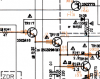
I found where the 47 ohm resistors are placed on newer amps. They put them where a jumper was on the older amps. These are R241-244. What I don't understand is why they are 47k resistors in my amp, not 47 like the schematic...

Also notice the unpopulated cap location on the old and it's populated on the new. These are caps from the TSB

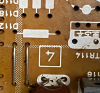
TR114 is out of the old amp because I am removing glue.

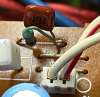
Old amp by TR113/114 Notice the two parallel jumpers:
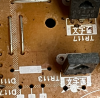
upload_2021-12-23_21-0-11.png
upload_2021-12-23_21-0-27.png

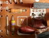
On my higher SN amp:
upload_2021-12-23_21-1-14.png
upload_2021-12-23_21-1-53.png
 
Last edited:
Probably the safest thing to do is implement the TSB as written on the old amp, but part of me wants to document the differences between my new amp and the old amp and then update the old amp to be the same as the newer amp. That could be painstaking and easy to miss something. So far it looks like the PCBs are the same.
 
I found where the 47 ohm resistors are placed on newer amps. They put them where a jumper was on the older amps. These are R241-244. What I don't understand is why they are 47k resistors in my amp, not 47 like the schematic...

Incorrect. Those two 47K resistors are R245 and 246. They are one of the small differences between an M-80 and an M-85. They are not part of the TSB. They are in the feed to the base of TR115 and 116 (Vbe multiplier circuit for bias control), from the Auto Class A circuit. They should be 47K. See the M-85 schematic. These resistors could prevent damage from propagating to the Auto Class A circuit, in the event of a failure where a bias transistor TR115, 116 becomes a short, by limiting the current from the Auto Class A transistors TR127, 128 respectively.
 
Last edited:
Incorrect. Those two 47K resistors are R245 and 246. They are one of the small differences between an M-80 and an M-85. They are not part of the TSB. They are in the feed to the base of TR115 and 116 (Vbe multiplier circuit for bias control), from the Auto Class A circuit. They should be 47K. See the M-85 schematic. These resistors could prevent damage from propagating to the Auto Class A circuit, in the event of a failure where a bias transistor TR115, 116 becomes a short, by limiting the current from the Auto Class A transistors TR127, 128 respectively.
Ah, yes that makes sense. I was wondering why M-85s still have 47 ohm resistors tied to the TR legs then. I will snip the parts of the SM later, but I was confused because the SM calls one of these resistors out as the 47 ohm.

Thank you for your help, and I appreciate your explanation of what the parts do in the circuit as well. I am learning about how amps work right now and reading Bob Cordell's Designing Audio Power Amplifiers.
 
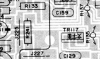
Here is what led me to think those resistors were the 47 ohm. On the schematic is shows R241 as 47.
upload_2021-12-24_12-2-37.png

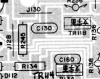
Then on the PCB diagram I found R241 here. The location that is the jumper on my old amp but the 47k resistor on my new amp. This is mislabeled, this should be R246.
upload_2021-12-24_12-4-41.png
 
No R245/246 in the M-80 SM.

So it looks like my higher SN amp has been updated to the M-85 SM level. If the PCBs are the same, then it should be reasonable to identify all the changes between my old amp and the updates at the M-85 level. I have a working M-80 with all the changes plus the M-85 SM. With those two things I should be able to identify all the changes and then be able to make them to my older M-80. Your thoughts on this approach?
 
Yes, I have those. The M-80 with TSB is the one that @brutal marked up. The thing is that this will leave the amp different than how the later amps are updated. I know this is an assumption, but if Yamaha made more and different changes that they applied to the M-80s they produced and into the M-85 then that is probably better than the original design with just the TSBs.
 
Last edited:
Ok, I have had a little time to get back to this, and reviewing this thread I am getting a better understanding of what is going on here and reviewing some of the things y'all have told me is making more sense.

On the TSB items I see how to implement them all and my updated amp and M-85 SM have them all except for R347-350 and C347-350. I am working on figuring this out from what @Arc deTriamp told me. On my newer amp the resistors and caps are not implemented on the foil side, and it's hard to see the component side, but I am still investigating.

In addition to the TSB, my newer SN amp and the M-85 service manual have:
R241-244 47ohm resistors
R245/246 47k ohm resistors

Is it possible that the resistors added in addition to the TSB remove the need for the R347-350 and C347-350 in the TSB? R347-350 and C347-350 do not seem to be on my newer amp or in the M-85 SM that I can find so far.
 
There a number of errors in the schematics and in the parts lists for both M-80 and M-85.
Thanks, you and Avionic have been spot on, it has just taken me a bit to see it for myself. I wish there was a doc that had the list of updates Yamaha started applying in the factory.
 
There a number of errors in the schematics and in the parts lists for both M-80 and M-85.
That should have said "There are a number of errors in the schematics..."

Anyway, as @avionic said, an M-85 is an M-80 with all of the TSB mods. Ok, Yamaha also added also added R245 and 246, replacing jumper wires that were in the M-80, otherwise they are the same as far as I have seen.

None of the updates, including the TSB, change the performance of the amp in any measurable or audible way. The TSB mods were aimed at reducing the scope of damage when something goes wrong, aka Chernobyl. These amps are not prone to failure, aside from that which results from the DSBG. These are fantastic amps.
 
I believe they are located on the APS thin strip circuit boards.

Not according to the TSB. I am looking at my M-80 serial # 11454 as a reference, but this might not be a good idea. The TSB is for serial #'s below 02401, so is it possible that there is a different TSB for serial #'s above 02401 or that the changes were done in the factory and are different than what is in the TSB?

The TSB copy I have is not very good. The schematics are blurry. But the schematic marked up by @brutal seems to be identical to what is on the TSB.

Yes, on one amp I've seen that actually had these caps, they were soldered to the top (foil side) of the APS circuit board. They were presumably added at the factory, being the light green caps, polyester, that Yamaha used in other locations for these amps. But they did not add the 33 ohm resistors on that particular amp.

If I recall correctly, to add the 33 ohm resistors and 0.01uF caps specified in the TSB, you must remove the short jumper wires that connect the supplies to the driver transistors, and replace them with the parallel combination of the resistor and cap. You can do this in various ways. On one amp, I soldered the resistor to the cap, then soldered the assembly in place of the original jumper wire. On another amp, I installed the cap in place of the jumper, then added the resistor on top (foil side) of the APS board, thinking that I could replace the resistor, if necessary, without removing the APS board.

Ok, so this finally is making sense to me. The schematic shows TR119/120 and TR125/126 on the Main Circuit Board, and the TR1xx implies that. Sheepishly I have to admit that I have been searching for these TRs for longer than I like to admit. I finally caught up to what you are telling me by realizing that these TRs hang off the APS power circuit boards. The SM PCB layout diagrams don't show these TRs like they show them on the Main Circuit Board. I'm embarrassed that I didn't realize this, but perhaps documenting this will help someone else in the future.

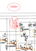
Notice TR119 right there next to TR117 on the schematic on the Main Circuit board:
upload_2021-12-26_20-3-8.png

Also notice that the TRs on the heat sinks connected to the Power Supply Circuit Boards 3 and 4 are not shown or noted:
upload_2021-12-26_20-5-5.png

Like they are on the Main Circuit board:
upload_2021-12-26_20-6-22.png

Now that I finally see the where TR119 is I can understand how R347-350 and C347-350 could be implemented on the Power Supply Circuit Boards 3 and 4. Makes sense that they are called out in the 3xx range too.
upload_2021-12-26_20-13-26.png
 
Posting for posterity now.

Started disassembling my low SN amp, low and behold someone has been here. Turns out TR126 has been replaced. Looks like the tech added the parallel resistors and caps 347-350, but nothing else of the TSB. Maybe the repair happened before the TSB? Who knows. Just like @Arc deTriamp said, replaced the jumper.
upload_2021-12-27_19-57-52.png

After surveying my two M-80's, here is the list of updates they each have:
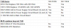
upload_2021-12-27_20-1-34.png

Course of action:
SN 01836
Definitely update with the rest of the TSB items.
Unsure about adding the M-85 updates, but thinking I should.

SN11454
I think I am going to leave as is. R and C 347-350 weren't installed and I don't see any hint of them on the M-85 SM.
 
Last edited:
M-80 and M-85 utilize the same part number printed circuit board.
This appears to be true for the Main Circuit Board (1), but the Power Supply Circuit Boards (3) and (4) on my older SN unit are different than the boards on my newer SN unit. This might explain the lack of R and C 347-350. Perhaps they made the chance on SN 02401?
 
That is from the M-80 SM. Interesting that on the M-85 SM they show those same part #'s as ass'ys.
upload_2021-12-30_9-27-57.png

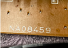
On the bigger boards there appears to be pcb part #s like this: (Did they drop the 0 at the end?)
upload_2021-12-30_9-31-10.pngupload_2021-12-30_9-31-33.png

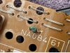
But on the power suppy boards there are not part numbers, just these:
upload_2021-12-30_9-32-48.pngupload_2021-12-30_9-33-9.png

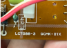
I think that the LC7588 is the number for the product, as it appears on all the boards. Although the main board has LC7590. I am not sure what GCMK-81X signifies. It's a little blurry, but from pics on this forum from another thread the numbers are GCMK-77X. My later SN unit has the same 77X, I just can't get a good picture of it.
upload_2021-12-30_9-48-14.png
 
Back
Top Bottom