• The move to the new server is done. There are some software and database maintenance updates in process. This has us passing the hat around to help out. We appreciate any donations. Seriously, even a dollar helps. The payment page may be found here - https://www.audiokarma.org/support.html

M-80 Restore

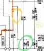
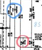
Ok, back at this one. On some of the M-80 threads and in the M-85 manual, C164 is called out as 47µF 25V BP. But the cap I pulled out is a 100µF 25V Black Gate. It's called an error in the SM, but this early SN M-80 is built that way. Another choice. Keep it as build, or update to the M-85 spec? Seems like this cap may affect idle current adjustment? Perhaps this cap changes the idle current adjustment between SN 11051? (Interesting that this cap actually has failed. My component tester shows it as 30pF. So far only failed component found.)
upload_2022-9-17_21-23-16.png


M-80 SM
upload_2022-9-17_21-22-34.png

M-85 SM
upload_2022-9-17_21-23-54.png
 
Last edited:
Ok, back at this one. On some of the M-80 threads and in the M-85 manual, C164 is called out as 47µF 25V BP. But the cap I pulled out is a 100µF 25V Black Gate. It's called an error in the SM, but this early SN M-80 is built that way. Another choice. Keep it as build, or update to the M-85 spec? Seems like this cap may affect idle current adjustment? Perhaps this cap changes the idle current adjustment between SN 11051? (Interesting that this cap actually has failed. My component tester shows it as 30pF. So far only failed component found.)
View attachment 2667179


M-80 SM
View attachment 2667178

M-85 SM
View attachment 2667180

Either way you should be fine. This cap won’t affect your idle current magnitude, Yamaha might have changed it to 47uF to cut costs, they probably thought they didn’t need 100uF for M-85 (just a guess). I’d stick with the original value installed at the factory.
 
Last edited:
Either way you should be fine. This cap won’t affect your idle current magnitude, Yamaha might have changed it to 47uF cut costs, they probably thought they didn’t need 100uF for M-85 (just a guess). I’d stick with the original value installed at the factory.
Yeah, I'm conflicted. I have been going down the path of updating this to the most current spec known. I have a newer M-80 here to check against too. So far here is my list of changes I know about. This is how these units were found.
upload_2022-9-18_8-52-4.png
 
Last edited:
Yeah, I'm conflicted. I have been going down the path of updating this to the most current spec known. I have a newer M-80 here to check against too. So far here is my list of changes I know about. This is how these units were found.
View attachment 2667409

At the end of the day, it’s your call. Just remember though that the latest isn’t always better, I have seen many instances of cost-cutting as the models evolved, especially starting early eighties.

For C164, it forms a low pass filter with the 3.9K resistor right behind it (or the R-equivalent of the circuit at that point to be exact) which cleans the negative supply voltage it sits on. I can’t read the value of that supply line voltage on my miserable schematic. The cut off frequency for that filter is just f(Hz) = 1 / (2 x Pi x Rx C) . The higher the C value, the lower the cut off frequency and a cleaner DC line. LOL … that’s why you have those huge capacitors always hanging from the supply lines. I’d go with 100uF.
 
Last edited:
There are some subtle differences between the M-80 and M-85. On the 85 the circuit around C-164 has been redesigned to add a 470p cap, C101 and resistor R103. Can’t say why, but it’s there. Unless you add C101, I’d keep C164 as is (although, as @Sparkplug says, it will probably not matter).

F622CE0A-C068-47A3-AFCB-8B026144DA68.jpeg

1BFFED1C-46A8-46EF-A617-05E9E340F016.jpeg
 
Last edited:
There are some subtle differences between the M-80 and M-85. On the 85 the circuit around C-164 has been redesigned to add a 470p cap, C101 and resistor R103. Can’t say why, but it’s there. Unless you add C101, I’d keep C164 as is (although, as @Sparkplug says, it will probably not matter).

View attachment 2667485

View attachment 2667486
Thanks, good point, I need to study the schematics closer. It seems like there is justification for the R241-244 and R245/246 changes, but the C164 is more complex. Best to keep it as originally or do the full due diligence to understand the rest of the circuit.
 
There are some subtle differences between the M-80 and M-85. On the 85 the circuit around C-164 has been redesigned to add a 470p cap, C101 and resistor R103. Can’t say why, but it’s there. Unless you add C101, I’d keep C164 as is (although, as @Sparkplug says, it will probably not matter).

View attachment 2667485

View attachment 2667486

Well, as it turns out this amp does have C101,102 and R103,104. And the Caps are listed in the M-80 parts list. They must have made an error and omitted it from the schematic. I do have a 100µF 50V Silmic II cap that fits. I might just stay with what was installed. Still a curious situation.
upload_2022-9-18_14-13-35.png

From M-80 SM:
upload_2022-9-18_14-10-45.png
 
Here's a weird one.

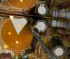
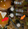
C111 seems to be installed with the polarity reversed from the factory (Red Arrow). I am 99% sure the amp was in original condition when it came into my hands. On my other M-80 C111 is installed according to the polarity on the silk screen, and nobody has mentioned an error here. So I think I will install according to the silk screen. Weird that the factory got it wrong though?

C164 is correct according to the silk screen on the pcb (Orange Arrow), But as noted in this thread (https://audiokarma.org/forums/index...-if-you-are-servicing-a-yamaha-m80-85.591887/) the polarity is in error. I guess that is what makes a Bipolar a nice choice here. But, if the schematic is correct, I traced the traces to the components and it does appear that the polarity is reversed. There are so many errors on the schematic though. Resistors in the wrong location etc. etc. I'm thinking of going with the 47µF Bipolar now. Also since the original cap here was the only component I have found bad so far, I'd like to not get this wrong.

Could the factory have installed two caps in the wrong polarity?

upload_2022-9-18_15-59-17.png
 
Last edited:
Of note is that the Main Circuit Board rev on both M-80s I have are the same, so I believe the traces are all the same. My working assumption is that if the pcbs are the same, and I review all the parts and changes and make them the same, then, well, they'll be the same. I agree with @Sparkplug that all newer revs may not be better, but in the case of the M-80 reducing the effects of a Chernobyl event and knowing which idle current value to use on this old amp after being updated makes me want to go with the latest and most common among this crowd.
 
Last edited:
There are some subtle differences between the M-80 and M-85. On the 85 the circuit around C-164 has been redesigned to add a 470p cap, C101 and resistor R103. Can’t say why, but it’s there. Unless you add C101, I’d keep C164 as is (although, as @Sparkplug says, it will probably not matter).

View attachment 2667485

View attachment 2667486
I downloaded the schematic for M-85 and took a quick look. The 470pf or C101 is independent of C164, they only connect to the chassis ground on one end. It forms another low pass filter with R103 and the equivalent resistance of R102 (can’t read the value) and VR1. Another LPF is present at the very input too, this one, based on the values given, has a cut off frequency of roughly 730kHz. What Yamaha is exactly doing with these I can’t tell. Limiting input noise? Maybe.

What I’m sure of is that C164 has nothing to do with them.
52B993B6-9E0C-488E-A551-DD8552FA568A.jpeg

Disclaimer: I hate low res. schematics
 
I downloaded the schematic for M-85 and took a quick look. The 470pf or C101 is independent of C164, they only connect to the chassis ground on one end. It forms another low pass filter with R103 and the equivalent resistance of R102 (can’t read the value) and VR1. Another LPF is present at the very input too, this one, based on the values given, has a cut off frequency of roughly 730kHz. What Yamaha is exactly doing with these I can’t tell. Limiting input noise? Maybe.

What I’m sure of is that C164 has nothing to do with them.
View attachment 2667929

Disclaimer: I hate low res. schematics
I hate low rez schematics, too.

Thanks for the analysis of the circuit. I find this type of analysis to be very informative.
 
I hate low rez schematics, too.

Thanks for the analysis of the circuit. I find this type of analysis to be very informative.

You’re most welcome. The slow setting epoxy advice (C-6 knob) worked wonders, thank you.

One of these days I am going to enter one channel of one of these amps into LTspice and see what pops out. Then changing values of individual components will directly show any changes in the output.

What I’ll never do is question institutions like Yamaha, Sansui, and alike … they were at the top of their game and some still are.
 
What I’ll never do is question institutions like Yamaha, Sansui, and alike … they were at the top of their game and some still are.
Fully agree! What the engineers did, even under the influence of the bean counters, is amazing. I strive to get a better understanding of why they did it. They left clues, but the reasons are lost to time.

I would be pleased to own a modern Yamaha integrated amp (if I didn’t have several vintage ones). And I’ve recommended them to others who are not handy with a schematic or a soldering iron.
 
I downloaded the schematic for M-85 and took a quick look. The 470pf or C101 is independent of C164, they only connect to the chassis ground on one end. It forms another low pass filter with R103 and the equivalent resistance of R102 (can’t read the value) and VR1. Another LPF is present at the very input too, this one, based on the values given, has a cut off frequency of roughly 730kHz. What Yamaha is exactly doing with these I can’t tell. Limiting input noise? Maybe.

What I’m sure of is that C164 has nothing to do with them.
View attachment 2667929

Disclaimer: I hate low res. schematics
Thanks Sparkplug, as Semanon has said, the explanation of what the circuit does is much appreciated. I also appreciate @Arc deTriamp comments when he explains what the circuits do.

Low res schematics are not nice, but worse are the errors and with omittances. As I was trying to figure out what the polarity of C164 should be I noticed that there is an error where R188 is on the other side of C112. (This is right below the +B Supply text you added)

Based on this schematic, polarity of C164 is indeed marked incorrectly on the silkscreen, but with so many errors on the schematic it makes me question the polarity marking of C164 on the schematic. I think i am going to install a bipolar, so it doesn't matter, but it would be nice to know if staying with the original polar cap.
 
Last edited:
Back
Top Bottom