• The move to the new server is done. There are some software and database maintenance updates in process. This has us passing the hat around to help out. We appreciate any donations. Seriously, even a dollar helps. The payment page may be found here - https://www.audiokarma.org/support.html

M-80 Restore

Thanks Sparkplug, as Semanon has said, the explanation of what the circuit does is much appreciated. I also appreciate @arcdetriamp comments when he explains what the circuits do.

Low res schematics are not nice, but worse are the errors and with omittances. As I was trying to figure out what the polarity of C164 should be I noticed that there is an error where R188 is on the other side of C112. (This is right below the +B Supply text you added)

Based on this schematic, polarity of C164 is indeed marked incorrectly on the silkscreen, but with so many errors on the schematic it makes me question the polarity marking of C164 on the schematic. I think i am going to install a bipolar, so it doesn't matter, but it would be nice to know if staying with the original polar cap.

Before making a final decision, I’d measure the voltage at the 3.9K 2W resistor and C164 junction. If it’s positive which it should be, then you can safely install another polar electrolytic in its place. I’d need to see physical proof that it is indeed the +B line the C164 is sitting on. Personally, I would not go with non-polar (no + or -) type caps.
 
Before making a final decision, I’d measure the voltage at the 3.9K 2W resistor and C164 junction. If it’s positive which it should be, then you can safely install another polar electrolytic in its place. I’d need to see physical proof that it is indeed the +B line the C164 is sitting on. Personally, I would not go with non-polar (no + or -) type caps.
Yeah, I get it. But why do you think they spec's a BP then? Assuming the BP in the M-85 parts list stands for BiPolar. Seems like if they just wanted to change the value they wouldn't need to make it BP too.
upload_2022-9-19_8-30-10.png
 
Before making a final decision, I’d measure the voltage at the 3.9K 2W resistor and C164 junction. If it’s positive which it should be, then you can safely install another polar electrolytic in its place. I’d need to see physical proof that it is indeed the +B line the C164 is sitting on. Personally, I would not go with non-polar (no + or -) type caps.
Out of interest, I'll measure voltages on my working M-80, the unit under the knife is completely disassembled.
 
Yeah, I get it. But why do you think they spec's a BP then? Assuming the BP in the M-85 parts list stands for BiPolar. Seems like if they just wanted to change the value they wouldn't need to make it BP too.
View attachment 2668074

Bipolar means two poles, + and -. At least that’s the standard I’m used to in my engineering life. Doesn’t the cap you took out have a negative pole marking? The schematic shows it too. The ones you’re referring too are known as electrolytic non-polar, meaning no poles, can be used either direction. Different people might use different nomenclature.
 
Last edited:
Bipolar means two poles, + and -. At least that’s the standard I’m used to in my engineering life. Doesn’t the cap you took out have a negative pole marking? The schematic shows it too. The ones you’re referring too are known as electrolytic non-polar, meaning no poles, can be used either direction. Different people might use different nomenclature.
Well, the SM is less than complete or accurate, so I am making the assumption that the BP in the M-85 signifies Bipolar. As you can see in this snip that FE is used in the part number for FE Mica Cap. Plus is seems that the consensus in this thread is the C164 is a Bipolar. Assuming Yamaha engineers made a choice to go bipolar. (https://audiokarma.org/forums/index...-if-you-are-servicing-a-yamaha-m80-85.591887/)
  • Capacitor C164: 47uF/25V Bipolar --> R2B-100V470MI5 Mouser. It’s a little big (100V), but fits well. R2B-25V470MI5 (25V version) was not available when I placed the order. Be careful, the service manual indicates a 100uf 25V polar capacitor, that’s wrong. There is also an error with the silkscreen on the board for this capacitor (polarity marks are reversed). So if you install a polar capacitor following the polarity marks, it will start to bulge on top…
Yes, the cap I pulled from my M-80 is polar, and is also 100µF. It would be interesting to know if any late M-80s or M-85s came from the factory with bipolar C164s. I'm not sure where the consensus in this thread that C164 is bipolar came from. I will see if I can find the original C164 in my other later SN M-80. When I recapped it I didn't know this was a change.

upload_2022-9-19_10-59-7.png
 
Found a pic of my SN 11454 M-80. Looks like a bipolar (Orange Arrow). I will go look through the pulled parts tub and hopefully find it.

Also confirms the polarity of C111 and C112, and my earlier SN 01836 had C111 polarity backwards. BTW, the amp was in working condition when I acquired it and before I started this project on it.

upload_2022-9-19_11-29-50.png
 
FWIW, I Found the cap that I pulled out of my SN 11454 amp, it is indeed bipolar, and I am 99% sure it was factory installed.
View attachment 2668210

Well, there you have it, just follow what was in there and you’ll be fine. Both will work, a non-polar (bi-polar to you) or a polar in the right orientation. BTW, we’re you able to measure that voltage mentioned before? Is that really a +B line? LOL … with these schematics you can never be sure.
 
or a polar in the right orientation.
M-60/65 uses a 100µf/25vdc in that position. All the M-80/85 I've worked on ( 15-20 perhaps) have had the 47µf/25 N.P. in that position. I did a rework, a while back , on a " Legendary Amps " M-85 where he "Skip" had replaced it with a 100µf/25 " Silmic II " polar cap. It had literally " blew up ".....

http://legendaryamps.com/

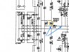
Thanks for the information Avionic, puts the repair/overhaul issue here to rest as far as I’m concerned. I do wonder, however, why a polar cap would blow up in that position. Also that Zener diode (encircled below) right next to the cap looks forward biased! Why not just use a regular diode, Zeners are usually reverse biased to provide voltage stability.

BTW, do you recollect what kind of voltage you were measuring (if you did) at points indicated below? Is that a positive B line these components are fed by? And what’s its voltage? Thanks for any light you might shed on these points.
96FEF7E9-BB8E-4161-87F4-1567A91D1C6D.jpeg
 
Last edited:
Thanks for the information Avionic, puts the repair/overhaul issue here to rest as far as I’m concerned. I do wonder, however, why a polar cap would blow up in that position. Also that Zener diode (encircled below) right next to the cap looks forward biased! Why not just use a regular diode, Zeners are usually reverse biased to provide voltage stability.

BTW, do you recollect what kind of voltage you were measuring (if you did) at points indicated below? Is that a positive B line these components are fed by? And what’s its voltage? Thanks for any light you might shed on these points.
View attachment 2668589
I will get my working M-80 out and measure at those points.
 
M-60/65 uses a 100µf/25vdc in that position. All the M-80/85 I've worked on ( 15-20 perhaps) have had the 47µf/25 N.P. in that position. I did a rework, a while back , on a " Legendary Amps " M-85 where he "Skip" had replaced it with a 100µf/25 " Silmic II " polar cap. It had literally " blew up ".....

http://legendaryamps.com/
Thanks Avionic, you also said that all the M-80/85s you have worked on all had the TSBs installed. Perhaps that cap was updated at that time too? This M-80 was manufactured prior to the TSBs and had the 100µF 25V polar Black Gate there just like the M-60/65. It does appear that the silkscreen is in error, so if Skip installed a polar cap according to the silkscreen maybe that is why it blew up. @amr2 mentions in his thread about repairing M-80/85 that if you polar cap there according to the polarity marks it will start to bulge. I wonder why the Black Gate in my M-80 didn't bulge. Perhaps the Black Gates fail differently? The Black Gate I pulled was definitely bad.
 
Thanks for taking the time. I’m fed up with this schematic and the info on it …
I'm also going to open up my M-65 to see if the Black Gate is in that amp too. (Just for fun!)

I will need a couple days to do this though, gotta get my parts order done for this amp first!
 
I do wonder, however, why a polar cap would blow up in that position
He probably installed it ass backwards....I couldn't tell.. The cap was destroyed foil and fuzz all over.. Or it was a bad cap from the get go.
 
Thanks Avionic, you also said that all the M-80/85s you have worked on all had the TSBs installed. Perhaps that cap was updated at that time too? This M-80 was manufactured prior to the TSBs and had the 100µF 25V polar Black Gate there just like the M-60/65. It does appear that the silkscreen is in error, so if Skip installed a polar cap according to the silkscreen maybe that is why it blew up. @amr2 mentions in his thread about repairing M-80/85 that if you polar cap there according to the polarity marks it will start to bulge. I wonder why the Black Gate in my M-80 didn't bulge. Perhaps the Black Gates fail differently? The Black Gate I pulled was definitely bad.

If the silkscreen is wrong and one puts in a polar cap backwards, that’s reason enough for bulging and even a blow up. The reason I asked about those voltages was to get to the bottom of that problem.
 
I'm also going to open up my M-65 to see if the Black Gate is in that amp too. (Just for fun!)

I will need a couple days to do this though, gotta get my parts order done for this amp first!
All the power to you … the most important thing is to find out if that B line is in fact positive, at what voltage, and as a result the silkscreening accuracy, then everything will fall in place. (We hope:D)
 
All the power to you … the most important thing is to find out if that B line is in fact positive, at what voltage, and as a result the silkscreening accuracy, then everything will fall in place. (We hope:D)
Agreed if installing a polar 100µF cap is the choice. I think the safer and more accepted route is to install the bipolar. To tell you the truth I already installed a UES in that position because I have those in stock, but that could easily be reversed.

I would like to understand the polarity of C164 just to be complete.
 
Back
Top Bottom