You are using an out of date browser. It may not display this or other websites correctly.
You should upgrade or use an alternative browser.
You should upgrade or use an alternative browser.
M-80 Restore
- Thread starter Asmodeus2112
- Start date

Asmodeus2112
Super Member
Good question. What do you replace them with? I have been using Silmic II.Million dollar question....Why did Yamaha use a " BlackGate" for C168 ( 100µf@6.3v ) <-----------relay time delay in the protect circuit. ??

Sparkplug
Super Member
Million dollar question....
This response was deleted since it erroneously referred to an unrelated part of the circuit involving C164 and not C168.
Last edited:

UKL -- It is used for the RC time constant for the protect relay delay. No audio path there.Good question. What do you replace them with? I have been using Silmic II.
Funny story... I had a bag full of 100µf @ 10v UKL's. Somehow I must have mixed in a few 10µf @ 100v into the same bag. Oops.. I was stumped for a bit that it took about 35-40 sec for the protect relay to click.. WTF

Last edited:
Asmodeus2112
Super Member
I'm sorry to ask such basic questions that have been asked before. I have searched and I know Avionic has answered this question for me before... I can't find flame proof carbon film resistors. Is there a known source?
If not, is it acceptable to use flame retardant carbon film or flameproof metal film?
What's the best practice, and these are not fusible in the M-80, right?
If not, is it acceptable to use flame retardant carbon film or flameproof metal film?
What's the best practice, and these are not fusible in the M-80, right?
Asmodeus2112
Super Member
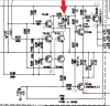
Thanks for the information Avionic, puts the repair/overhaul issue here to rest as far as I’m concerned. I do wonder, however, why a polar cap would blow up in that position. Also that Zener diode (encircled below) right next to the cap looks forward biased! Why not just use a regular diode, Zeners are usually reverse biased to provide voltage stability.
BTW, do you recollect what kind of voltage you were measuring (if you did) at points indicated below? Is that a positive B line these components are fed by? And what’s its voltage? Thanks for any light you might shed on these points.
View attachment 2668589

Sparkplug
Super Member
Dear Lord, so it is a negative supply line, the schematic says +B if I read it correctly. The polarity of C164 in the schematic is correct, if one chooses to use an electrolytic polar cap, since the E (Chassis Earth) is positive with respect to -17.9V … just what I was suspecting. Thanks for taking the time to take these numbers, very revealing indeed.
If silkscreen designation agrees with the schematic, that is correct too. If you end up using a Bi-polar (non-polar), it won’t matter.
Asmodeus2112
Super Member
I think you are looking at C164 in your analysis, which I appreciate and learned something from. The Black Gate Avionic is referring too is C168 in the Muting/Protection circuit.That’s one good reason, another could be, If I’m guessing right, the voltage at the non-ground side of C168 is ~0.6V because D159(can’t read the label, it’s a blob and if I zoom in, it becomes a bigger blob) is forward biased with a lot of current flowing through it and the 2W 3.9K res next to it. It sets up the voltages on the sources of Tr101 and Tr102 dual FETs through R111 and R112. C168 keeps those voltages clean, stable, and protect against fluctuations due to relay time delay, etc.. Asmo’s voltage measurement might help explain.
Sparkplug
Super Member
I'm sorry to ask such basic questions that have been asked before. I have searched and I know Avionic has answered this question for me before... I can't find flame proof carbon film resistors. Is there a known source?
If not, is it acceptable to use flame retardant carbon film or flameproof metal film?
What's the best practice, and these are not fusible in the M-80, right?
Is it a resistor in the power supply board? Which one? What’s the wattage? Flameproof metal film should work too, so will a metal oxide although noisier. I usually up the wattage one knot (3W for 2W for example) when changing power resistors because you can get higher wattage (safer) resistors in surprisingly small packages these days as compared to 30 or 40 years ago.
Sparkplug
Super Member
I think you are looking at C164 in your analysis, which I appreciate and learned something from. The Black Gate Avionic is referring too is C168 in the Muting/Protection circuit.
View attachment 2669384
Then follow what he suggested, I wouldn’t put an electrolytic polar here either, not a 6.3V one anyway.
Asmodeus2112
Super Member
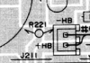
If you trace the line where is says +B back it leads to -HB. And on the layout you can see that -HB is connected to R221 which is connected to R226. There are some - voltage listings on other components connecting from that line too. Certainly appears to be negative.Dear Lord, so it is a negative supply line, the schematic says +B if I read it correctly. The polarity of C164 in the schematic is correct, if one chooses to use an electrolytic polar cap, since the E (Chassis Earth) is positive with respect to -17.9V … just what I was suspecting. Thanks for taking the time to take these numbers, very revealing indeed.
If silkscreen designation agrees with the schematic, that is correct too. If you end up using a Bi-polar (non-polar), it won’t matter.

Sparkplug
Super Member
I think you are looking at C164 in your analysis, which I appreciate and learned something from. The Black Gate Avionic is referring too is C168 in the Muting/Protection circuit.
View attachment 2669384
Thanks for pointing it out, you’re right, I was fixated on C164. I have deleted my response to @avionic on this cap as well.
Asmodeus2112
Super Member
Well, Avionic was no longer discussing the C164 polar/bipolar choice, he was simply questioning why Yamaha would choose to put a Black Gate in the protection circuit. Seems like a wrong choice.Then follow what he suggested, I wouldn’t put an electrolytic polar here either, not a 6.3V one anyway.
Asmodeus2112
Super Member
NO WORRIES! I learned from what you described is happening at that point in the circuit.Thanks for pointing it out, you’re right, I was fixated on C164. I have deleted my response to @avionic on this cap as well.
I was going to say. Your schematic must be a helluva lot different than mine.Thanks for pointing it out, you’re right, I was fixated on C164. I have deleted my response to @avionic on this cap as well.

Asmodeus2112
Super Member
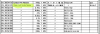
Looking for parts to replace the 1/4W Carbon Flame Proof resistorsIs it a resistor in the power supply board? Which one? What’s the wattage? Flameproof metal film should work too, so will a metal oxide although noisier. I usually up the wattage one knot (3W for 2W for example) when changing power resistors because you can get higher wattage (safer) resistors in surprisingly small packages these days as compared to 30 or 40 years ago.
Sparkplug
Super Member
I was going to say. Your schematic must be a helluva lot different than mine.
Oh that’s very kind … I too would think I must be on some potent drugs … you should have said something … like what the fluck are you talking about …
Sparkplug
Super Member
Looking for parts to replace the 1/4W Carbon Flame Proof resistors
View attachment 2669405
A 1/4W or even a 1/2W flameproof metal film will be just fine. I’d go with 1/2W, they’re so small these days …
Asmodeus2112
Super Member
Since I have my working M-80 on the bench I thought I may as well check the idle current. Just want to verify that I am reading the technical bulletin about the check points correctly. It's the top of R157 to R159 and R158 to R160. Which looks like this, right?

Sparkplug
Super Member
Is this what you’re following? R153, R155 and R154 and R156?Since I have my working M-80 on the bench I thought I may as well check the idle current. Just want to verify that I am reading the technical bulletin about the check points correctly. It's the top of R157 to R159 and R158 to R160. Which looks like this, right?
View attachment 2669410