• Please note that Audiokarma will be offline briefly for updates early on Monday morning, September 28th.

M-80 Restore

Since I have my working M-80 on the bench I thought I may as well check the idle current. Just want to verify that I am reading the technical bulletin about the check points correctly. It's the top of R157 to R159 and R158 to R160. Which looks like this, right?
View attachment 2669410
No...... Those are not the correct TP´s..
 
index.php


These are the correct test points for M-60,M-65, M-80 and M-85

The service manual procedure is not correct....

Your measuring the voltage across only one of the emitter resistors.
 
Last edited:
A 1/4W or even a 1/2W flameproof metal film will be just fine. I’d go with 1/2W, they’re so small these days …
If you are replacing a fusible resistor ..Do not up the wattage ! That would be like replacing a 2A fuse with a 4A fuse...
 
If you are replacing a fusible resistor ..Do not up the wattage ! That would be like replacing a 2A fuse with a 4A fuse...
Does Yamaha mean fusible by listing a resistor as “flame proof” or “frame proof” (Japanese can’t pronounce L)? I didn’t see any fusible resistor mentioned in the parts list … unless I missed it … :rolleyes:
 
index.php


These are the correct test points for M-60,M-65, M-80 and M-85

The service manual procedure is not correct....

Your measuring the voltage across only one of the emitter resistors.
Wow, really? Even after they issued a service bulletin updating the procedure?
 
Personal preference.. Point is mute .. The have reached the EOL..
Obviously so … I’m curious, very interested to learn what aspect of Silmic you don’t care for. Is it the highs, the lows, the mid tones? That’d be very valuable info for me. Thanks.
 
Wow, really? Even after they issued a service bulletin updating the procedure?
Ok, I see that the procedure for the M-65 matches the test points that Avionic is telling me, and that from the schematic point of view that all makes sense, I just find it hard to believe that Yamaha could screw this important setting up, and then send out an update continuing to propagate the error.

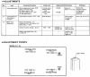
From M-65:
upload_2022-9-22_15-17-37.png
 
If you are replacing a fusible resistor ..Do not up the wattage ! That would be like replacing a 2A fuse with a 4A fuse...
On the resistors, the SM says flameproof carbon film, but I have seen you refer to the 47Ω fusible resistors on for R241-244 on the 4 TO-126 transistors in the VAS circuit.

Would this be a good choice: https://www.mouser.com/ProductDetai...=sGAEpiMZZMtG0KNrPCHnjZGsCasP8tbCE5dYe3O/h2E=

For the other flameproof resistors that are axial/radially bent, are they ideally fusible too?
 
C111 seems to be installed with the polarity reversed from the factory (Red Arrow). I am 99% sure the amp was in original condition when it came into my hands. On my other M-80 C111 is installed according to the polarity on the silk screen, and nobody has mentioned an error here. So I think I will install according to the silk screen. Weird that the factory got it wrong though?

I'm replacing parts on my M80 as well (glue issue of course). Looking for C111 & C112 replacements on mouser and found 6.3volts 220uF replacements:
https://www.mouser.com/c/passive-co...le=Radial&voltage rating dc=6.3 VDC&instock=y

My question is, do I want bi-polar/non-polar? Also what do some of the other measurements mean like '0.2L/S' '5x11 20% 2LS' ? Thanks and bare with me as I'm still learning.
 

Attachments

  • Mouser C111 C112.png
    Mouser C111 C112.png
    112.2 KB · Views: 4
Back
Top Bottom