
Asmodeus2112
Super Member
At the end of the day es macht nichts, but I like to understand what is going on before I make changes.


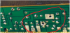

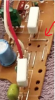


Hi Asmodeus, nice work. I was looking at your pictures of the way you mounted the main filter caps. I have the same capacitors in my m80 restoration as well. How did you get them to line up with the pcb board slots to solder them? the original capacitors have narrower spacing between the + and - terminals as compared to these screw type connections.I purchased the 33000µF caps with the stud that are referenced on other threads here about M-80s. Cut the stud off. Also note that one of the caps listed has high screw terminals but the other has low. Space was very tight, but it fit. I was nervous about the stud contacting the chassis back panel. The stud is a negative terminal and on one of the caps will be -88V. I put a big square of Formex as an insulator on the back wall.
View attachment 2350748
View attachment 2350749View attachment 2350750View attachment 2350751
Hi Asmodeus, nice work. I was looking at your pictures of the way you mounted the main filter caps. I have the same capacitors in my m80 restoration as well. How did you get them to line up with the pcb board slots to solder them? the original capacitors have narrower spacing between the + and - terminals as compared to these screw type connections.
I am trying to make custom brackets that will slot into the pcb board but the on center positioning of the new caps wont line up. did you bend your fittings or did you use hook up wire screwed into the capacitors then soldered to the board. Any tips would be appreciated boy its tight to fit these in. no room for error. thanks Rob

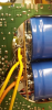
Ok, I would be concerned about the connection to the screw terms. I like the ring terms because the lock in so tight. I wish it was possible to solder hook up wire right to the terminals, but solder doesn't stick. The eight connections to the caps are the only thing that is used to mount the pcb.thanks that explains it, I tried the same thing all day today but they never lined up, the triangle shape would help. thanks for telling me. Due to the lack of room I am going to use good quality hook up wire or as Avionic suggested just now solder wick braid. thanks for posting the pictures
Congrats on your project! (I was the original Guest125 and DBx5 in these threads and somehow I've forgotten the logins to those original accounts)Ok, I would be concerned about the connection to the screw terms. I like the ring terms because the lock in so tight. I wish it was possible to solder hook up wire right to the terminals, but solder doesn't stick. The eight connections to the caps are the only thing that is used to mount the pcb.
The PCB is the R-Side 77x revision and was originally stuffed with Mylar. Due to the orientation you cannot see the resistors hidden by the large bias resistors.I was reading about @Guest125 M-80 updates on this thread: https://audiokarma.org/forums/index.php?threads/another-m-80-restoration-project.832592/page-2
And noticed he added film caps, but on my SN 01836 power supply board there are no though holes at those locations. On the M-85 those are jumpers. I am not sure exactly why Guest125 added those caps.
View attachment 2437308

I was reading about @Guest125 M-80 updates on this thread: https://audiokarma.org/forums/index.php?threads/another-m-80-restoration-project.832592/page-2
And noticed he added film caps, but on my SN 01836 power supply board there are no though holes at those locations. On the M-85 those are jumpers. I am not sure exactly why Guest125 added those caps.
View attachment 2437308

One thing to keep in mind when utilizing the M-80 in modern equipment setups, not unlike I do, where the line output of the source device is 0dB/1V rather than the original 1.55V of the C-80. The sensitivity mismatch can be easily corrected by replacing R101 and R102 with a 1% audio quality 1/4W resistor. Mine were originally 220Ω if I'm remembering correctly, and were replaced with 150Ω to allow full 0dB (full output) when input with 0dB/1V sensitivity from my AVR.
The sensitivity of the M-80 is not established by R101 and R102. The sensitivity is determined by the closed-loop gain, and that is set by the values of the feedback resistors R187, 188 (430 ohms) and R117, 118 (12K ohms). The closed-loop gain is therefore (12K + 430)/430 or 28.9. To reach rated output of 250W into 8 ohms requires sqrt(250*8) = 44.72 VRMS. The input voltage required to reach rated output power will then be 44.72/28.9 = 1.55 V, which is the input sensitivity, exactly as quoted by Yamaha.
The M-80 input pots VR01, VR02 are voltage dividers between the left and right inputs and TR101, 102. They can be used to reduce the sensitivity of the amp, but cannot increase it. Nor can changing the values of R101 and R102. These resistors (R101, 102) provide a ground return path for the input signal and prevent the input from floating off of zero if unconnected. They are 2.2M ohms! Decreasing their value will only reduce the sensitivity of the M-80, and reducing their value to 220 ohms will likely load down your source or preamp too. You can easily check the sensitivity by turning off the speaker outputs and observing the meter reading while you apply a known input signal.
In short, there is no modification that will increase the sensitivity of an M-80 to 1.0V. If you desire to increase the sensitivity you will have to place a preamp of some kind between your AVR and the M-80. You'll need new eardrums too and probably new speakers, if you are running an M-80 at or near full power.

My bad, the resistors are R103 and R104. The original value is listed in table 14 in the schematic (this is a revised M-80 schematic provided by Yamaha) and depending on the model is listed to change the input sensitivity. I know for a fact that this does change the input sensitivity as I do own one. Reducing the original 220Ω to 150Ω will revise it's sensitivity to 1.0V/0dB. (you do not turn off the speaker outputs, you must check with no load on the outputs) The M-80 0dB meter calibration can be checked by inserting a 1kHz tone, 2Ω scale at 34.5V at the speaker output. (and if the sensitivity could not be changed, 0dB (1kHz@1V) from the AVR would never obtain 34.5V) I'm sorry, but in short, you are not correct in your assertion that the sensitivity cannot be changed, or that you will require some additional voltage amplification between the AVR and the M-80. (and frankly, the comments concerning blowing speakers or eardrums is a non-sequitur and insulting)
View attachment 2498927
The assumption that R103 and 104 are input attenuators is incorrect. Changing their values will have no effect on the sensitivity or gain of the M-80. I will come back to that subject, but first there are a couple of other things that I would like to address briefly.
For the record, the M-80 meters do operate with the speaker outputs disabled. When the outputs are disabled by the front panel speaker selector switches, the entire amplifier is still active but the speaker terminals are disconnected by the output relays.
The M-80 impedance switches change the calibration of the meters to indicate the power that would be dissipated in a load of the selected impedance, but the switches have absolutely nothing to do with the amplifier operation itself. The selection of the nominal load impedance only affects the meter reading and does not change the amplifier voltage gain or sensitivity in any way. Also, it is a voltage amplifier - the output voltage looks like an enlarged version of the input voltage, regardless of load (within the amp's capabilities). In other words, the output voltage ideally, and practically in all but the most extreme circumstances, only depends on the input voltage and not the load impedance. Another way to look at it is that the amplifier output impedance is very low, so that the output voltage is essentially independent of the load impedance and is therefore independent of the current flow.
As I stated before, the assumption that R103 and 104 are input attenuators is incorrect. They are in series with the gates of TR101 and 102, which are 2SK389 JFETs. The input impedance of a JFET is extremely high - so high that the input (gate) current is essentially zero, less than 1 nanoamp for the 2SK389. Consequently, by Ohm's Law, there is no voltage drop in these resistors, and they do not attenuate the input signal, period. The only attenuation in the front end of an M-80 is in the input potentiometers*. As I stated before, there is no way to increase the sensitivity of an M-80 (short of changing the feedback resistors, which would be imprudent for several reasons). Btw, input impedance is determined by the end-to-end resistance of the input potentiometer, independent of the pot setting.
*G (Europe) and B (Great Britain) models (250V mains) have an additional RC network at their inputs to attenuate RF. The resistors are spec'd at 560 ohms, and attenuate the input by about 0.24 dB, about 2.7% loss on the M-80, as they add to the resistance of the voltage divider tapped by the wiper of the input pot. Again, there is essentially zero current in the gates of TR101 and 102, and thus there is no current in the wiper of VR101 and 102, nor in R103 and 104.
The actual purpose of R103 and 104 is to damp out RF that may find its way to the gates of TR101 and TR102. Yamaha specified two different values for R103 and 104 (Schematic Note 14) for different regional models. The models using 250V mains feature 470 ohm resistors, while the others use 220 ohm. Universal models that I have seen also feature 470 ohm resistors in spite of the 220 ohm entry in the table on the schematic. Notice also that there is only one sensitivity specified in the M-80/85 service manuals, common to all regional models, 1.55V, (although as noted some models G and B have slightly reduced sensitivity due to the RF filter at the input). That (1.55V) is the input required to drive the output to rated power of 250W into 8 ohms.
Again, the sensitivity is the input voltage required to drive the amplifier output to the voltage at rated power, into the stated load. For the M-80, the sensitivity is specified for 250W into 8 ohms.
One could actually replace R103 and 104 with jumpers, or 100K resistors, and it would make no difference whatsoever in the sensitivity of this amplifier. There is a tradeoff in the resistor value, however. Resistors contribute noise, and more resistance will add more noise - clearly undesirable. On the other and, a lower resistance will be less effective in absorbing RF. The noise contributed by a 220 or 470 ohm is quite low, while it is still effective in dissipating the RF picked up from surroundings, which can resonate with the combination of the gate capacitance and the inductance of the input circuitry.
One may feel free to disagree with this analysis, but know that I have also verified the theory by altering the value of R104 in my amp. I changed R104 from 470 to 235 ohms by adding another resistor in parallel. As circuit theory predicts, the change made absolutely no difference in the amplifier gain or sensitivity, zero. One can also verify this by measuring the voltage at each end of R103 or 104 while applying a test signal. One will not see any difference between the two measurements, again because there is essentially zero current in the gates, and thus zero current (and zero voltage drop) in the resistors in series with the gates.
For anyone out there wishing to measure the voltage gain of their amplifier, apply a constant amplitude test signal such as a sinusoid, and measure the voltage at both the amp input and at the output, with the same instrument. The gain is of course, the output amplitude divided by the input amplitude. The sensitivity is measured similarly - the sensitivity is the input voltage that is required to drive the amplifier to the particular voltage that represents maximum output. The sensitivity can also be calculated by dividing the output voltage at maximum power by the voltage gain. As I stated, at 250W into 8 ohms, the output voltage will be 44.72 volts. I would not consider a VU meter on an AVR to be the gold standard for voltage measurement, and it is not capable of measuring the amplifier output for comparison. I suggest a good digital multimeter, or a scope. An output of 34.5V is indicative of an input voltage of about 1.2V for the M-80, given its gain of about 28.9.
Input sensitivity and amplifier gain are not the same, and you are confusing the two. The output voltage for 0dB reference (no load) is specified by Yamaha, not me, so please go argue with them, not me. R103 and R104 are not RF filters BTW. (and I do know a little about RF as I do hold a General Class FCC license) Good luck in life...
