• The move to the new server is done. There are some software and database maintenance updates in process. This has us passing the hat around to help out. We appreciate any donations. Seriously, even a dollar helps. The payment page may be found here - https://www.audiokarma.org/support.html

Maggie 9304 Amp Threads?

Thanks for the update on the silicone caulk.

As an update, I've had a bit of a set back. I needed to replace the 220K resisters that sat right under each 6EU7 as their resistor value had drifted high. Instead of cutting off and J-hooking to the lead left behind, I tried to remove the solder and connect to the socket. Well, I knew better and ended up breaking socket lead #7 on channel 1. Now, I've got more work ahead of me...ugh....I know better!

So, now I need to order some parts and thought that I'd go ahead and replace the small ceramic cap at that bridges pin 8 and 9. The schematic I have is labeled 100mmf. I have a brain challenge with this value conversion. I this 100 picoFarads?

Hate setbacks.
 

Attachments

@gadget73 thanks so much for the quick response. I think I have 100pf caps hanging around. Hope so, one less thing to order. Thanks for the words on replacing the wafer sockets; it will probably be easier in the end after all. Thanks again!
 
Hey y'all....

I've had a chance to get a few parts sourced and have the 9304 rewired. I have the power transformer wired as Dave has recommended with the second 6.3v winding in series with the primary winding. With NO tubes in place, the High Voltage was 295V and the other voltages were 6.58v and 5.4v.

I put all the tubes in and slowly dialed it up on the variac. No smoke....good sign :).

With each of the output terminals connected to a 100watt 4ohm load, I took the following measurements:

314v at from the 40uf electrolytic
304.4v for the B+ at the 10K ohm resistor/30uF electryolytic
292.7v on the other side of the 10k ohm resistor

All four output tubes were similar at pins 7, 9 and 3
Pin 7: 302v
Pin 9: 304.7v
Pin 3: 10.8v

The 6EU7 were a little high on pin 7; measurements are as follows:
Pin 7: 222.1v
Pin 8: 0
Pin 9: 2.3V
Pin 6: 210v
Pin 5: 2.29v


I have some HORRIBLE 4ohm speakers that I'll be replacing. However, I used them to connect to the amp. I used a CD player with a splitter into channel 1 and 2.
The good news is that it made sound and it was music. However, it was very quiet and noisy.

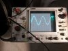
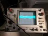
I connected to the scope with a 180 cycle frequency on the signal general. I had the amp flipped upside down to access the line directly with the signal generator alligator clip. On channel 1 I was able to follow the signal from the 6EU7 to the output transformer out the back of the amp. That scope image is channel one below.

I did the same for channel 2 with bad results.....horrible image with nothing but noise.

I let the system cool and then switched the output tubes, making sure that I put the one that were in channel 1 into channel 2.

The issue followed the output tubes and then channel 1 was bad on the scope. BTW, I'm a total poser on the scope, but it has helped me solve issue with my guitar amp builds in the past.

Thoughts on replacing tubes? Should I get a pair or just throw out the baby with the bathwater and replace them all. I wish I had a tube tester, but I don't. All of the tubes seem very likely original to the amp.

PS....don't pay attention to the fuse. I had to bypass for now as I neglected to get the right physical size fuse for the holder I got.....doh.

Thanks for any thoughts?

Bart
 

Attachments

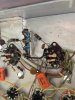
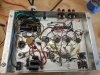
  • Updated Maggie.jpg
    Updated Maggie.jpg
    162.8 KB · Views: 24
  • Channel 1.jpg
    Channel 1.jpg
    111.9 KB · Views: 24
  • Channel 2.jpg
    Channel 2.jpg
    108.6 KB · Views: 23
I didn't alter any of the original circuit, just replaced parts. My rationale was that it should work decent as original designed. I want to minimize any alteration so I can better trace where issues arise.

Any thoughts on the voltages and tube question?
 
If this is stock and does not have the balance pot (not the hum balance, a second one), it will need the 390 ohm resistors installed to sub for the missing balance pot that is on the preamp chassis. The circuit is not complete without either the pot or the resistors.
 
Ahh.....got it. That is what I was missing in my understanding of the whole balance pot situation as I thought it was already present. I'll good back to D G's post to make this modification.

However, the tube switching does make me think I might have a tube issue. Seems like it would be less expensive to make the balance modifications first and then thing about tube replacement.

B
 
Thoughts on replacing tubes? Should I get a pair or just throw out the baby with the bathwater and replace them all. I wish I had a tube tester, but I don't. All of the tubes seem very likely original to the amp.

Seems like it would be less expensive to make the balance modifications first and then thing about tube replacement.

I'd be very surprised if the output tubes were bad, remember those units and if they are original tubes were circa early 60's and back then most folks who owned a console weren't cranking it up and in the process abusing the amps.

Try the balance mods first it would be a shame to get rid of those original tubes as most of all the 93XX series I've come across they tested quite good.

You mentioned guitar amp builds you did in the past so I'm assuming you might know other guitarists in your local community or general region. If so why not reach out and see if any of them have a tube tester I gotta a believe you can find someone to let you test them or test them for you.

Post some pics of them who knows they might even be Mullards
 
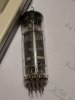
Got it. Here's the tube. I was just going through my resistor stash to try to come up with either a series or parallel combination that will get close to 390 ohms.....haha Always something to order with this hobby.

Thanks for the feedback.....no pun intended.

B
 

Attachments

  • 6bq5.jpg
    6bq5.jpg
    70.5 KB · Views: 21
The original pot was 750 ohms, so the perfect value would be 375. If you happen to have a 330 and a 47, thats closer than the usual 390 ohm used.
 
Thanks for the thoughts. I went through my stash and had a combination, wired in parallel, that would get within 5%. However, I only had three instead of 4. I've got some on order for cheap.


As for the tubes, yes, they are all original, made in Germany and look identical to the one I pictured.

I have been ignoring the hum pot as I thought it was used as a virtual center tap for the 6 volt wiring but looks like that's not the case. Weird.

Thanks for all the input. I'll have what I need soon to do some more investigation of modifications.

Switching the both tubes from channel 1 to 2 and see the changes follow the tubes makes me feel like that they are involved...

Bart
 
Update. You guys saved me a lot of time and headache!!

I rummaged around in my resister pile again this evening. I found four 750 ohm resisters. As an experiment, I soldered two pair in parallel to make a 375 ohm resistor pair. I used jumper wires into the spots that Blackdog had in his picture (Big Thanks!!). Damn if it didn't work OUTSTANDINGLY. Little amp is loud, even through the crappy little bookshelf speakers. For input, I was using a CD player without a preamp.

I'm now getting visible amplification on the scope.

If anybody has a good recommendation on speakers that they like for the Maggie, please let me know your opinion.

I'll post some pictures once I get it fully put together. I've got a nice wood enhancement for the chassis that I've already made while waiting on parts and stuff.

Thanks again everyone!

Bart
 
Are the OP tubes still an issue? also when you finish her up with the wood base and all be sure to post pics
 
Back
Top Bottom