• The move to the new server is done. There are some software and database maintenance updates in process. This has us passing the hat around to help out. We appreciate any donations. Seriously, even a dollar helps. The payment page may be found here - https://www.audiokarma.org/support.html

Maggie 9304 Amp Threads?

Hey Dswankey....tubes do not seem to be an issue. I've not taken measurement to calculate plate dissipation but I'll do that for kicks. I'll definitely post pics...should have it all soldered up this weekend.

Thanks again for all the help to AK!

B
 
IMG_20200423_152702.jpg

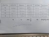
Above are the measurements of all the output tubes. Looks like V2 and V3 are matched and running a little hot while V5 and V6 are in a better PD range. If this was a guitar amp, I'd probably adjust the bias resistor for each tube but I'm pretty sure these amps are not supposed to work that way. The bias resister is a new one that I placed and is measured at 99.5 ohms.
 
Barton -- If I may, something is a little screwy here. You've measured the DC resistance for each half of the primary winding in your output transformers, as well as the voltage drop across each half, and determined your plate current. No problem with procedure, but here's what should be investigated:

1. Collectively, you're indicating that in plate current alone, your output tubes are drawing 169.4 mA -- which is awfully high given the rather low plate (and by reasoning the screen) voltages your tubes are running at.

2. If you add in a collective additional 16 ma to account for screen current, that means your output stages are collectively drawing 185.4 mA -- again, very high for a set of four 6BQ5 tubes.

3. That much current equates to 18.4 volts across a 99.5Ω cathode bias resistor, yet in your post #27, you state there is only 10.8 volts at the cathode, for a collective current of 108.5 mA through all four tubes, which is a much more typical Magnavox operating level.

Clearly there is no agreement here between the calculated plate and screen current, versus measured cathode current. I would bet that #3 is much more closer to the truth, but certainly worth investigating.

Dave

 
Hi Dave! Thanks so much for your input! I did these measurements for each of the tubes individually for the plate. The above resistances are from Pin 8 of the rectifier to Pin 7 of each of the 4 output tubes with the corresponding voltage drop. The plate voltage was measure on pin 7 to ground on each tube.

I just went back and actually measured the voltage drop across the 99.5 ohm resistor and it was 9.16 volts. Using ohms law, this calculates to 0.0921 Amps or 92.1 mA for all 4 tubes or an average of 23mA of plate current per tube.

Does this help to make sense of my numbers?

Again, thanks so much for the input!

Bart
 
No Choke Resistance to Pin 7.jpg

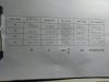
Great point. This time I measured the resistance from just after the choke in the power section (where the B+ goes to the output transformer center taps) to pin 7 for all four tubes to get "R" above. I then measured the voltage drop for this same "distance" for each tube to get "V" above. I recalculated the plate current for each tube and then used the same measure Plate Voltage (Pin 7 to ground) for each tube. I then calculated the Plate Dissapation. If this is done correctly this time, it seems like a much different situation than before. I totally forgot about the resistance from the choke.....THanks.

Thoughts?
 
I'm pretty sure its the tube. I took out V5 and used some 1000 grit sandpaper to lightly clean the pins and remeasured.....still low. I don't think there are any wiring or soldering issues, to see if it was the tube, I switched the stronger V3 with V5 and the previous plate voltages followed each tube.

Bummer. But thanks for all the input in helping run this down. It was fun as I'm more used to single ended output tube.

Bart
 
Last edited:
Don’t judge it until you get some matched tubes in it. I agree with you about SE. Even in stock form, the little 86xx amp has some magic that the bigger PP doesn’t quite have.
 
Bart -- Purely as a matter of procedure, when figuring plate dissipation, the voltage measurement is always be made from the plate, to the cathode. Sometimes the cathode is (effectively) grounded (as in fixed bias amplifiers) and sometimes the cathodes are stood on a resistor as in the Magnavox design. In this case, the 10 or so volts won't change your calculations much but still, for absolute accuracy, when figuring Pd levels, its the voltage as measured between the plate and cathode that counts.

I hope this helps!

Dave
 
if you want to confirm its the tube, move it to another spot and verify the measurements move with it.
 
Hey Gadget. Yep. Did that. And the low voltage followed the tube. It's the tube.

Thanks everyone. I'll get some pics of the wood body soon.
 
Front 9304.jpg

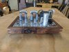
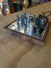
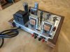
Hey Y'all......here is the finished wood wrap that I put on it. This was a scrap rough piece of walnut that I got for a few bucks at Woodcraft last year. I finished the sides and made the knot the highlight of the front (actually it just worked out that way and I thought I'd make the best of it).

I used epoxy to stabilize but did not want to make it flush on the front....left it open. Joints are mitered with a very light colored poplar spline.....all I had at the time. The finish on the wood is simple wipe on Danish Oil; after dried, I put a Johnson's paste wax coat on it. I put 1/2 inch rubber feet on the bottom. I don't have a pic of the pilot light on, but it was super bright....so I used a resistor, I think 100 ohms, to allow it come on but not be a spotlight calling Batman.

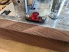
I also used walnut to hold the switch and pilot light. I cut a strip on the table saw and shaped it with the sander and then by hand.....I really like the way these turned out.

Overall, I think it sounds fine and looks great. Thanks again to all the great suggestions and help from you all!

Bart
 

Attachments

  • Front angle switch 9304.jpg
    Front angle switch 9304.jpg
    108.5 KB · Views: 29
  • Pilot light 9304.jpg
    Pilot light 9304.jpg
    118.7 KB · Views: 28
  • Back 9304.jpg
    Back 9304.jpg
    123 KB · Views: 29
Amp with a single cathode resistor calls for a closely matched quad of tubes. If you change to a 200 Ohm cathode resistor per pair, two matched pairs will self bias more closely. (with the tubes you have now, the lower ones will draw more, higher ones less). FOUR cathode resistors will make the even closer, at the cost of some power. (and you need bypass cap per resistor in each case).
 
Hey Tom...Thanks for the input. I see your point and I am planning to get a new set of tubes in the future. The two tubes of the 4 I have that have a little more life would probably do nice in a small push pull scratch built future guitar amp :).

I'm glad to be at a point that I need to look for a decent set of speakers.

B
 
Dude that wood base looks really nice!!!! congrats. Sorry I couldn't be of more help with regards to the speaker question. I'm sure one of the guru's here could straighten that out for you
 
Back
Top Bottom