• The move to the new server is done. There are some software and database maintenance updates in process. This has us passing the hat around to help out. We appreciate any donations. Seriously, even a dollar helps. The payment page may be found here - https://www.audiokarma.org/support.html

Marantz 1180DC restoration

cbusuttil

Active Member
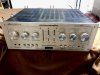
Hello! I thought i d share my ongoing restoration on this wonderful integrated amp. First impressions; quite modular and easy to work on since many of the modules are plug-in! the amp is in decent shape apart from the bass and balance sliders which at some point snapped and have the metal part missing.

843D610B-A0B3-4A77-9464-0113B35B7CB4.jpeg
 
Last edited:
Register to hide this ad
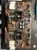
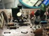
The amp section (P700) received new capacitors and transistors Mostly KSA992 and KSC1845 instead of the 2SC1775/2SA872. The PNP differentials were matched as best as i could. Those unobtainable 2SK109 were replaced with LSK389B which did a fantastic job. MV-1 varistors and thermistors looked okayish so i left these alone. I also checked all resistors and found them to be within spec even when i put a heat gun to check for any drift. all 4x WZ-310 zeners rated 31V at 500mW were replaced with a closest match at 30.9v at 500mW, 2% (part number: NZX30C,133). A word of caution: Do not put 1.3w zeners as these might not work in their active region and thus will not regulate properly; 500mW is more than plenty and these hardly get any warm!! All signal diodes, such as 1S2471 and 1S1555 were replaced with 1N4448. Anyway, all components were sourced from Mouser.The 4x W06B diodes were replaced with UF4007 respectfully, which are rated at 1amp, as opposed to the 750mA original ones. This is how the amp looked originally…

FDA8226A-51BF-4907-BBB6-0EA8BDA80512.jpeg 1F79BD26-F9CC-4148-ACAB-D4A96D82A721.jpeg
 
Last edited:
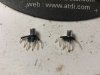
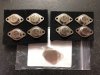
Here are the LSK389B jfets. These are TO-71 and thus needed to be shaped in order to fit.

ACB1CAAF-57A0-4B84-B439-130620E6BD4D.jpeg 826F93A7-93CA-4386-8A44-9120BE63A400.jpeg 0F444947-6AE5-4181-BAEE-3F61170C494A.jpeg
 
Last edited:
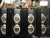
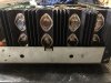
New MJ15022/23G - Hfe curves seemed more consistent between the NPN and PNP so i opted to use these instead of the popular MJ21193/94G. New mica insulators too!

AB1AA7BE-B5C2-4773-B641-D66EDEA3A069.jpeg
 
Last edited:
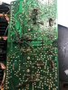
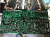
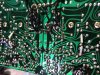
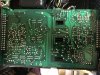
Amp pcb solder refurbished and lacquered for dust protection too! This pcb is full of corrosive glue!! So i painstakingly did remove all the glue to preserve the tracks

8607F667-4F12-4B7A-8EC3-36FB5B54640D.jpeg210534FF-E946-4194-B1A0-2555062119E2.jpeg
 
Last edited:
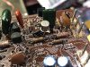
P700 Amp section ready for fitment!! It is strongly suggested that those 4x 22uF at 35v at the top of the PCB (namely C707,708,715,716) voltages be uprated to at least 50V instead of the original 35v, since these see an average of 31 - 33V (they are in parallel with the 31V zeners!!). Those 4X 47uF 63V capacitors located in the middle (C731,732,733,734) were uprated to 100V, long life ones as these see +-50V! . It is also suggested that C723 & 724 be replaced with long life (10000hours) capacitors rated at 63V as these are subject to lots of heat. In fact, what i did (after i took this photo) was that I left the capacitors leads as long as possible so that they protrude out of the heatsink area as possible, for better airflow. Marantz knew about this issue as in fact the original ones had long leads and thus were not soldered directly touching the PCB

Capacitors in audio path used are Nichicon KT 105 deg audio grade.

I must stress that the service manual is full of errors!! for example,CT09 and CT11 are shown as 33uF on the service manual, whereas in reality my amp was fitted with 22uF, even the connectors are labeled wrongly! Rely only on the values that the amp came with. Didn’t expect this from Marantz!!

08C94C3C-07E3-4291-89CB-63832236FF55.jpeg
 
Last edited:
I noticed the DC offset took a while to stabilize… even after the amp restoration. I mean, it starts at +250mV, goes to zero within 10 seconds then climbs back to -50mV and takes approx 10-15 minutes to go back to zero. once it’s zero, it stays that way, or say, within 5mV. I did disconnect the preamp etc but this issue remained. The only thing that is getting on my nerve is when the relay kicks in (circa 5 seconds and the dc offset is at around +100mV), you can hear a faint pop on the speakers. it’s faint. I do not know if this is the way the amp is or if it has got something funny going on… those MV-1 varistors? or those thermistors? i really do not know. anyone stumbled upon this issue on these amps? not to mention they run hot… a bit too hot for my liking. any insight would be greatly appreciated. this “issue” seems to be present on both channels. All tracks were checked as well and found to be okay. it’s mind boggling for sure.
 
Last edited:
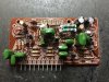
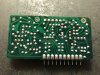
Filter board renewed with new transistors and capacitors. KSA992 & KSC1845 used here whilst the electrolytics used in the signal path are Nichicon Gold audio grade caps. Low ESR caps were used in the power supply…

95537B81-C95B-46E3-9A6A-850ABECB20E6.jpegF7D6B199-03E8-4151-A597-60AA92184050.jpeg
 
I got a bit carried away with work on this unit and i forgot to take a photo of the rebuilt component side of the preamp! Sorry! anyway, again, all KSA992 and KSC1845 transistors used. the 133 dual diodes were replaced with 2x UF4007 diodes soldered together. these were soldered onto the other side of the board along with new 7.04v 500mW 2% zener diodes (Part no: MTZJ7V5SA R0G, bought from Mouser) for easy access. the 7.04V zener diodes were the closest value i could find to the original WZ-071 7.1V ones. Another thing worthy of mentioning, is the 2x main filtering caps (470uF at 63v); these are better off being 80 or 100V as supply voltages in this section hover at around 55v!! In this case, i used Vishay low esr capacitors rated at 100V.

I kept the original transistors in the phono section, as I do not use the phono section anyway. However, I did replace the capacitors there.

91527AAC-AD43-4762-A907-180CE5773134.jpeg 2969548B-A858-4A8E-86AA-1883CAE62D4A.jpeg
 
Last edited:
Looks great!

I recapped mine back a few years ago now. From what I remember it was easy enough getting to the parts. Started out with a noisy transist. Still runs a little warm as it did before this service. Like you stated the DC offset settles down after a while on mine also.
 
Last edited:
Looks great!

I recapped mine back a few years ago now. From what I remember it was easy enough getting to the parts. Started out with a noisy transistStill runs a little warm as it did before this service. Like you stated the DC offset settles down after a while on mine also.

Thank you! much appreciated! indeed it is not difficult to source the parts! easy to work on too, except the pesky pre amp board... you have to dismantle the whole front or rear facade to get it off!! hmmm so yours also takes a while to settle on the dc offset? does it make any faint pops on the speakers when the relay is engaged?

Chris
 
No pops, quiet except for the relay clicking. The DC settles down in a short time. Minute or two IIRC. I let it warm up good before setting. Made up a pair of 5v muffin fans with the power supply plugged into the switched AC outlet to move air away from the output transistors. Seem to do this on most of my equipment in use.

The only issue requiring fineness was the pins on the board posted on post 9 that is behind the Mode switch. Getting them snug and secure with good connection in both channels.
 
No pops, quiet except for the relay clicking. The DC settles down in a short time. Minute or two IIRC. I let it warm up good before setting. Made up a pair of 5v muffin fans with the power supply plugged into the switched AC outlet to move air away from the output transistors. Seem to do this on most of my equipment in use.

The only issue requiring fineness was the pins on the board posted on post 9 that is behind the Mode switch. Getting them snug and secure with good connection in both channels.

I did fit a fan to blow up air, will upload a photo of it later! .. re. dc offset: That is my problem. DC offset takes a good while to settle down. once it settles down, it stays that way, (within 5mV). I can hear a slight pop when the relay engages and i cannot seem to find why the dc offset is taking so long to settle down!
 
No pops, quiet except for the relay clicking. The DC settles down in a short time. Minute or two IIRC. I let it warm up good before setting. Made up a pair of 5v muffin fans with the power supply plugged into the switched AC outlet to move air away from the output transistors. Seem to do this on most of my equipment in use.

The only issue requiring fineness was the pins on the board posted on post 9 that is behind the Mode switch. Getting them snug and secure with good connection in both channels.


i am also noticing that when i load the amp and the temperature inside gets really hot, the DC offset in one of the channels (the rear part of the amp, i.e the right channel) goes up to 30mV! the other one stays at approx 8 - 9mV... i am really lost here! any insight?
 
From what I have gathered this model runs warmer then most. Hence the additional help now of using the fans to move air out also. After all it is 90 WPC and eight TO3's ...could of used a bigger heat sink? You think!

I did not replace as many components as you have. Mine had a phono issue with a transistor popping. From there did the recap while inside and on the bench. Already had the capacitors.

Was it doing this before the service?
 
h
From what I have gathered this model runs warmer then most. Hence the additional help now of using the fans to move air out also. After all it is 90 WPC and eight TO3's ...could of used a bigger heat sink? You think!

I did not replace as many components as you have. Mine had a phono issue with a transistor popping. From there did the recap while inside and on the bench. Already had the capacitors.

Was it doing this before the service?


mmm thats the thing, im not so sure, but iirc hearing a faint pop when the relay engages…
 
okay we got somewhere… this thing seems to be be stemming from the pre amp section, or so it seems. when i isolated the pre amp there were no more pops and dc offset straight to -25mV. i am vaguely thinking some lack of grounding? as the preamp’s transistors and diodes are entirely new
 
I can't think of anything off hand other then checking to see if the preamp's voltages fluctuate. Or have some DC passing from there being amplified.
 
Narrowed it down to the little filter board. With this little board removed, there are No pops when the relay clicks. took out the board and i compared all of the new transistors with the old ones and their hfe is practically exactly the same. all resistors checked, and the electrolytics renewed but the problem persists!!! checked all connections and grounds, all seem to be okay. im really lost!!
 
Back
Top Bottom