You are using an out of date browser. It may not display this or other websites correctly.
You should upgrade or use an alternative browser.
You should upgrade or use an alternative browser.
Marantz 1180DC restoration
- Thread starter cbusuttil
- Start date

cbusuttil
Active Member
If that is the board behind the Mode switch. I had a time with getting good contact on the 90* attachment. Cleaned the pins and redid the solder connections and snugged it up tight.
Yes that is the board. I am thinking of soldering it permanently as those connectors are a nightmare!!
cbusuttil
Active Member
Was able to clean up the area and adjust it snug.
I was loosing a channel when having the issue.
You might be having a issue with the transistors not being a good match may be.
I really don't know. as I used very very similar ones to the originals; ksa992 and ksc1845 .... very strange. I might have to live with it the way it is ... I triple checked everything and all is okay .. those varistors and thermistors are a questionmark ... i dont have any substitutes for those ...
cbusuttil
Active Member
I only changed out the transistors in the phono section when under the hood.
No recalling the subs used in there.
Remember getting that board was a royal PITA getting just tight n right.
Yes!! especially when done in place. I am waiting for 2 used rheostats since mine are snapped. So far, so good. Im not that worried about that slight click when the relay engages ... i increased the delay to 6 seconds instead of the original 4.5 seconds ...it's a tad better.
cbusuttil
Active Member
From what I have gathered this model runs warmer then most. Hence the additional help now of using the fans to move air out also. After all it is 90 WPC and eight TO3's ...could of used a bigger heat sink? You think!
I did not replace as many components as you have. Mine had a phono issue with a transistor popping. From there did the recap while inside and on the bench. Already had the capacitors.
Was it doing this before the service?
bullseye! i feel that heatsink is a tad small indeed!! the little fan helps wonders in keeping the air around the pcb area a bit cooler!
cbusuttil
Active Member
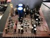
Relay board which also houses the peak indicator drivers. KSC1845, KSA992 replaced the 2SA872 and 2SC1775. 2SC945 were replaced with KSC1815, same pinouts. I used these since the 2SC945s that were originally installed measured lower gain. KSC1815 are slightly lower gain.
1S2092 were replaced with UF4007s; these have slightly higher parasitic capacitance (IIRC 17pF as opposed to 4pF) but i wasn’t worried about this since these are fitted in the peak indicators. Also, Trr (reverse recovery time) is on par with the original 1S2092, in the region of 100nS.
1S2473 were replaced with 1N4448. Trr is around the same, approx 4nS and approximate similar parasitic capacitance; 4pF
Again, DS131B dual diodes were replaced with 2X soldered UF4007 together.

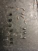
1S2092 were replaced with UF4007s; these have slightly higher parasitic capacitance (IIRC 17pF as opposed to 4pF) but i wasn’t worried about this since these are fitted in the peak indicators. Also, Trr (reverse recovery time) is on par with the original 1S2092, in the region of 100nS.
1S2473 were replaced with 1N4448. Trr is around the same, approx 4nS and approximate similar parasitic capacitance; 4pF
Again, DS131B dual diodes were replaced with 2X soldered UF4007 together.

cbusuttil
Active Member
I notice C234? is proud of the board a tad. Probably not a issue, have seen it be one in the past.
Where is it? cannot find it anywhere in the service manual

Where is it? cannot find it anywhere in the service manual
Sorry CE24?...
cbusuttil
Active Member
Sorry CE24?...
Yes indeed those were also replaced. the only thing i didnt replace in the entire amplifier are the resistors. I did check them for any thermal drift but were still within spec so i left them alone.
They should have put the linear power supply in a better place too; at least in a place where techs can instantly check the voltages etc. the way its put you have to diagnose semi blindly lol . This amp is really cramped inside… seriously cramped!! Even to diagnose problems on the amp while it’s working, is a nightmare, especially when probing with a meter or scope.
cbusuttil
Active Member
Other the doing a recap, when I go in like to replace a few as required old "good" parts at a time.
That way can tell right off if there was changes.
Every transistor (except the outputs) i pulled out was checked for hfe and i tried to match it as best as i could so as not to loose the circuitry dynamics and equilibrium, you know… i hate uncalled for surprises!! ha ha