• The move to the new server is done. There are some software and database maintenance updates in process. This has us passing the hat around to help out. We appreciate any donations. Seriously, even a dollar helps. The payment page may be found here - https://www.audiokarma.org/support.html

Marantz 1180DC restoration

Can you share what transistor substitutes you used first
yep sure:
Q721 originally 2sa914 ---> 2sa1220A
Q723 originally 2sc1953 ---> 2sc2690A
Q725originally 2sc1913 ---> 2sc2344. Also tried 2sc3298A with same result
Q727 originally 2sa913 ---> 2sa 1011. Also tried 2sa1306A with same result

both channels affected. However left channel (Q's quoted) is worse - only get to 10.30 on the volume before static distortion, whereas right channel gets to nearly 1.00pm before it distorts.
All components seem to have integrity and match side to side.

I did replace the MV1's with IN4004's yesterday. Three of the MV1's tested with forward resistance of 58kohm, the other with 465k ohm.(was on left channel. Matched the IN4004's for forward resistance at 56k ohm. Has made NO difference, although offset voltage is now +/- 1mV.

Any ideas on other substitutes that are available would be appreciated. I realise that the ones I subbed are obsolete, but I obtained them from WES in Australia, which is a reputable electronic warehouse that still has them, but nevertheless they may be dodgy.

Any suggestions welcome
 

Attachments

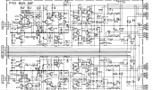
  • Screenshot P700.png
    Screenshot P700.png
    321.4 KB · Views: 12
How are the zener diodes on p700?
zener diodes have been replaced with new IN4148
Q749 to 752 diodes replaced with UF2005 which are faster equivalents to IN4004/In4007
Thermistors have not been replaced at this stage as cold they all seem to measure around 100ohm (Q745 to 748), but maybe once they are warm there are some issues?- possibly?

Small signal transistors replaced with A992 and c1845
 
Last edited:
There had been some dodgy work in the past with the medium power drivers. There was still one 2sc1953 and one 2sc1913 of the original 8. there was no matching from side to side, and the right channel was awful. There were obvious signs of past burning on front and back of P700 board, so I did a full recap and replace all suspect resistors. There is not much left to replace. Even so it sounds fantastic at lower volume levels, but something is accounting for the distortion on both channels, with left worse.
I also replaced the mosfet ICs 701 and 702 with the LSK389's with the same sensitivity as the 2SK109s removed.
 
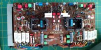
P700 Amp section ready for fitment!! It is strongly suggested that those 4x 22uF at 35v at the top of the PCB (namely C707,708,715,716) voltages be uprated to at least 50V instead of the original 35v, since these see an average of 31 - 33V (they are in parallel with the 31V zeners!!). Those 4X 47uF 63V capacitors located in the middle (C731,732,733,734) were uprated to 100V, long life ones as these see +-50V! . It is also suggested that C723 & 724 be replaced with long life (10000hours) capacitors rated at 63V as these are subject to lots of heat. In fact, what i did (after i took this photo) was that I left the capacitors leads as long as possible so that they protrude out of the heatsink area as possible, for better airflow. Marantz knew about this issue as in fact the original ones had long leads and thus were not soldered directly touching the PCB

Capacitors in audio path used are Nichicon KT 105 deg audio grade.

I must stress that the service manual is full of errors!! for example,CT09 and CT11 are shown as 33uF on the service manual, whereas in reality my amp was fitted with 22uF, even the connectors are labeled wrongly! Rely only on the values that the amp came with. Didn’t expect this from Marantz!!

View attachment 2515890
as a matter of interest did you replace the transistors around the heatsinks at all (Q721 - Q728), and if so what were your replacements? A later picture on the thread seems to indicate you did - or did you just put them back after cleaning?
 
i have been considering replacing the above transistor for Q721 and Q723 with 2sb649A and 2sd 669A respectively. Any thoughts? They have much greater current capacity and am wondering whether that is an issue as presumably circuit and power transistors should determine limits of current draw - or am I completely wrong about that? please let be know.
 
A
zener diodes have been replaced with new IN4148
Q749 to 752 diodes replaced with UF2005 which are faster equivalents to IN4004/In4007
Thermistors have not been replaced at this stage as cold they all seem to measure around 100ohm (Q745 to 748), but maybe once they are warm there are some issues?- possibly?

Small signal transistors replaced with A992 and c1845
a zener needs to be changed with a Zener can you double check what you used here?
 
and possibly for Q725 and Q727 with MJE15032G and MJE15033G respectively?? Grateful for any of your thoughts
I have found originals for these locations in the past i think these subs would work or perhaps ksa1381/ksc3503 - i hope someone else can confirm this for you in this location - similar for q721/3 i suspect ksa1381/ksc3503 works here.

Lastly - can you double check all the wiring to the pins on the bottom of the board have any snapped off causing a voltage drop?? This is a common problem with this board
 
A

a zener needs to be changed with a Zener can you double check what you used here?
Many thanks for this question - I had always thought that the IN4148 was a zener diode... but it is not!!! what a revelation - thankyou!! Its a small signal diode instead. I have some IN4747A zener diodes but need to check their characteristics to see if the will be suitable. NB it must have been the glass shell on the 4148 and red stripe that tricked me into thinking it was a zener.... this may be the problem if they are blocking the reverse voltage.
 
Many thanks for this question - I had always thought that the IN4148 was a zener diode... but it is not!!! what a revelation - thankyou!! Its a small signal diode instead. I have some IN4747A zener diodes but need to check their characteristics to see if the will be suitable. NB it must have been the glass shell on the 4148 and red stripe that tricked me into thinking it was a zener.... this may be the problem if they are blocking the reverse voltage.
I think you have found your problem please replace with a Zener diode with the same forward voltage plenty around keep us posted
 
A

a zener needs to be changed with a Zener can you double check what you used here?
I checked - and I haven't replaced the original Zeners.

However I checked them with an ohmmeter and Q731 has a forward and reverse resistance of only 100ohms. The other three(q732-Q734) all tested with a resistance between 5.6kohm to 8.5kohm in both directions. So If I replace Q731 then would probably replace all so they are matched.
The closest Zener I can find in voltage is IN4751A which is 30V 1W and 8.5mA - test current. The WZ310 specified is 31V 0.5W and 5mA test current.
So is this likely to be a satisfactory replacement given the low test current. Cant find any further specs on this, but it is available locally.

Just wondering about threshold voltage and whether 30V is close enough for this amp. next closest available is 33V (IN4752A)??.
 
I have found originals for these locations in the past i think these subs would work or perhaps ksa1381/ksc3503 - i hope someone else can confirm this for you in this location - similar for q721/3 i suspect ksa1381/ksc3503 works here.

Lastly - can you double check all the wiring to the pins on the bottom of the board have any snapped off causing a voltage drop?? This is a common problem with this board
Thanks for these recommendations. I will see if I can source here in Aussie land.
With respect to wiring to the pins - yes disastrous - when they break off and you dont notice. Fried some transistors and resistors several times. Now that I check for it, it is not an issue, but most are now soldered back on to terminal pins
 
I checked - and I haven't replaced the original Zeners.

However I checked them with an ohmmeter and Q731 has a forward and reverse resistance of only 100ohms. The other three(q732-Q734) all tested with a resistance between 5.6kohm to 8.5kohm in both directions. So If I replace Q731 then would probably replace all so they are matched.
The closest Zener I can find in voltage is IN4751A which is 30V 1W and 8.5mA - test current. The WZ310 specified is 31V 0.5W and 5mA test current.
So is this likely to be a satisfactory replacement given the low test current. Cant find any further specs on this, but it is available locally.

Just wondering about threshold voltage and whether 30V is close enough for this amp. next closest available is 33V (IN4752A)??.
I think the 30v is ok or you can join two together to make 31 go with a 1 percent tolerance version
 
Thanks for these recommendations. I will see if I can source here in Aussie land.
With respect to wiring to the pins - yes disastrous - when they break off and you dont notice. Fried some transistors and resistors several times. Now that I check for it, it is not an issue, but most are now soldered back on to terminal pins
Great stuff hopefully these suggestions are still on mouser or at Wes
 
The fact you isolated the power supply suggests potentially the transistor substitutions could be causing this issue as it’s common to both channels or something else that’s been replicated twice
 
Great stuff hopefully these suggestions are still on mouser or at Wes
Can get the 3503 on mouser but not the 1381. Only on Ebay in US - so would be a couple of weeks to get them.

Can get the 2sa1352 and 2sc 3416 from WES and a 30V zener with +- 10% tolerance on voltage. These will take 2 days to arrive.
Will let you know
 
Separate to this try find mv1 or find a thread here on which resistors to swap out to reset the bias when using 1n4148 once this issue is resolved the bias will be too high and will run even warmer than stock so that will need addressing too hope that helps
 
Separate to this try find mv1 or find a thread here on which resistors to swap out to reset the bias when using 1n4148 once this issue is resolved the bias will be too high and will run even warmer than stock so that will need addressing too hope that helps
OK thanks - I swapped the MV1s out with IN4004s and selected them to have the same forward resistance as the MV1s - - 56kohm and very close forward voltage.

At the stage the bias doesnt need much adjusting. Curious though is that the machine only runs warm with most heat coming from the medium driver trannies. Power transistors are quite cool - not much heat coming from the main heatsink.

I expect that once I swap out these medium transistors it will produce more heat as their dissapation is much lower (7W compaed with 20/25W) and so most heat will be transferred to the heatsinks to keep the transistors at a safe working temp. Some of the original transistors only had a dissapation of 0.1W - so the heat sinks were working very hard to dissapate - running very hot.
 
OK so I swapped out the 4 zeners with 30V 700mA 1Z30's. Didnt make a lot of difference, but the amp seemed somehow more stable.
So i then swapped out the A122A and the c2690A's with the A1352's and c3416's respectively. - left channel only as the surgery takes some time when the solder pads and part of the tracks have been destroyed.
Voila!!! Left channel now working perfectly. Swapped the same on right channel and YES!! Amp now running stable. Dont hear the presence of much distortion in signal or speakers until the 3pm mark on volume. Too loud to be around in a small room.
Heat wise i ran the amp at 12.30pm on the volume for 45mins and the heatsinks for the power transistors only reached a maximum of 45 degrees C so able to warm the hands on a cold day - not hot to the touch at all. This would seem to be a much better result in terms of heat control than others are reporting with original medium driver transistors.

So very pleased. now to polish and clean the amp and get it back to the client!!

I will post a pick of the completed power amp board below.
 

Attachments

  • signal-2025-05-26-122811.jpeg
    signal-2025-05-26-122811.jpeg
    136.2 KB · Views: 16
here is a link to the datasheets of the A1352 and c3416 for anyone interested. A very nice match to the originals. Sourced from WES in Australia
 
Back
Top Bottom