• The move to the new server is done. There are some software and database maintenance updates in process. This has us passing the hat around to help out. We appreciate any donations. Seriously, even a dollar helps. The payment page may be found here - https://www.audiokarma.org/support.html

Marantz 1200

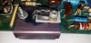
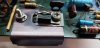
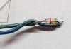
I had forgotten what the sockets looked like, but there does appear to be a yellow component melted on yours, between the sockets. This is the best pic I could find of mine (not great):
nwdFvMU.jpg


Is that the thermal diode that melted?
 
I would love to know exact production numbers, and all the details about the various versions.

Do you guys have this same chassis ground?
WZfhYt2.jpg
 
You still have your stock jumpers, and even the Aux 2 and Phono 2 termination plugs (or are they just caps?), yours was very well kept. Interesting to see you have the later style chassis ground, and the gain switch was changed to black.

Would be curious to know what serial number the 1200B model was introduced with.
 
Mine has the metal chassis ground, no plastic.

I am scratching my head as to what might have caused the left channel to blow up so spetacularly. All outputs are fried, and the heatsink is discolored.
 
Does your good channel make any noise?
Just put it on a gen and scope and got a beautiful waveform, 400Hz square wave without any bends. That channel is promising and will be my reference on this rebuild.
 
Interesting. So, mine might have some features of the B model while still cosmetically being a non-B.

The big change was the balance and volume pots and amp circuit. The 1200 had 100k and 250k pots. The 3500 and up had 25K and 50K. There are other small changes in power supply and other places.

Tony
 
I had forgotten what the sockets looked like, but there does appear to be a yellow component melted on yours, between the sockets. This is the best pic I could find of mine (not great):
Is that the thermal diode that melted?

I confirmed in the schematics - this is C801, never knew it existed. 0.1uF and it measures exactly that so one thing less to worry about.

upload_2021-4-7_18-57-14.png
 
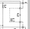
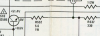
Circuit modification as per Addendum - add 5.6ohm 1W resistor in series with Q510's emitter. Installed new 2SC2344 Sanyo Audio Power Transistor NPN hFE=144.

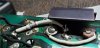
Added jumper for Q510's collector.

20210410_145243.jpg

As per new schematic:

Screenshot 2021-04-10 145502.png
 

Attachments

  • 20210410_141021.jpg
    20210410_141021.jpg
    79.8 KB · Views: 15
  • 20210410_145803.jpg
    20210410_145803.jpg
    70.3 KB · Views: 14
  • 20210410_145809.jpg
    20210410_145809.jpg
    62.1 KB · Views: 14
Last edited:
I am not seeing this mod this in the addendums that I have. I can see R552 added on the V2 and B schematic. Can you share where you are seeing it.

Tony
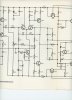
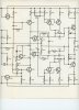
Sure, there is always a chance I am modifying the wrong version.Schematic027.jpg Schematic026.jpg Schematic025.jpg
 
Germanium diode is busted. New one looks better.
 

Attachments

  • 20210410_181003.jpg
    20210410_181003.jpg
    64 KB · Views: 21
  • 20210410_181545.jpg
    20210410_181545.jpg
    86.1 KB · Views: 20
  • 20210410_185615 (2).jpg
    20210410_185615 (2).jpg
    56.1 KB · Views: 19
Are you modifying your 3058 to update to the 3500 changes?

Tony
Correct. My theory is that this board got into a thermal runaway situation, and from the little I can understand of the changes they seem to help with that even though that is not explicitly stated in the manual.

My last resort will be to convert this into almost a B by replacing the diode/transistor with the transistor/transistor solution.
 
Back
Top Bottom