• The move to the new server is done. There are some software and database maintenance updates in process. This has us passing the hat around to help out. We appreciate any donations. Seriously, even a dollar helps. The payment page may be found here - https://www.audiokarma.org/support.html

Marantz 2010 project won't power on, need help troubleshooting

Aaron99

Active Member
Recently I have acquired a Marantz 2010 in decent cosmetic condition. It was known when I purchased it that it would not power on.

I put it on a DBT and I get no light at all. Do I need a less wattage bulb, it currently is a 75Watt incandescent. I have used the DBT successfully testing my 2220.
I tested the fuse with multimeter and there is continuity.

Popped the hood:
P800 no voltage on any of the jumper pins.
I replaced the electrolytic caps on the P800 board. With same capacitance and slightly larger voltage.

P600
There was a a couple of heated areas on the P600 board: R648, R650.

A resistor was replaced by previous owner(s): R639. It looks like it got hot under the resistor.

I replaced R648 and R650 with 3W 0.5ohm wirewound resistors which is what was in it and the service manual calls for.
I replaced R639 with a 220ohm metal film resistor.

No change. Still dead and doesn't light the DBT.

When plugged into DBT I measure 120VAC across the switched and unswitched outlet. This is the case with the power switch on and off. This seems odd that even with the power switch off that there is power on the unswitched outlet.

When testing the power switch, I test from ground to either contact and it measures 99VAC with switch on or off. Again, this doesn't seem correct to me.

Any thoughts on helping me save a baby Marantz?
IMG_20170225_174216.jpg
 
Register to hide this ad
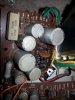
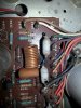
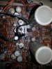
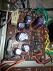
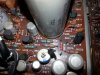
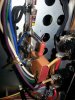
Here are some pictures of the 2010. I have recapped the P800 board, and replaced 3 resistors on the P600 board.
Before:
IMG_20170225_174138.jpg

Notice where the board got hot.
IMG_20170225_174148.jpg

Notice where the board got hot under R639. Someone had replaced it with a different resistor.
IMG_20170225_174156.jpg

After recap on the P800 board.
IMG_20170225_210331.jpg

R639 replaced
IMG_20170225_210359.jpg
R648 and R650 replaced.
IMG_20170225_213201.jpg
 
Last edited:
With the unit unplugged have you tested the switch for continuity? Can do it with the Ohm setting on a multimeter too. 99 volts does not sound right and that needs to be explored but it should work and light up with that I would think.

Ohm out both sides of the power cable too, should get a low reading but not zero.

Do this first and go from there.
 
Thank you for your troubleshooting help with this.

With the unit unplugged have you tested the switch for continuity? Can do it with the Ohm setting on a multimeter too. 99 volts does not sound right and that needs to be explored but it should work and light up with that I would think.
The switch measure O.L when off and goes to 0.01 ohm when switched on so it tests ok.

Ohm out both sides of the power cable too, should get a low reading but not zero.
Does this mean to test the power cable by connecting the lead to each prong and measure the ohms? If so, I measure O.L. which is the same when I measure another working Marantz.
I measured the power cable from either prong to the switched power outlet and it measures 0 ohms. So there is no resistance in the power cable.
 
The unswitched power outlet is supposed to be hot all the time. The switched only when the unit is turned on. The "no light at all" on the DBT sounds weird to me. Are you sure the bulb is good? 75W should be about right.
 
The unswitched power outlet is supposed to be hot all the time. The switched only when the unit is turned on. The "no light at all" on the DBT sounds weird to me. Are you sure the bulb is good? 75W should be about right.

Yes, I just tested the DBT on my 2245 and it lights bright, then dims as expected. When the 2010 is plugged in and switched on there is no light at all.
 
99 volts does not sound right and that needs to be explored but it should work and light up with that I would think.
I figured out why I was measuring 99VAC. I was measuring to the chassis ground. There is a resistor between the switched outlet and the chassis. When I measure the between the outlet it reads 123VAC.
 
You might want to re check your power board. Test the power resistors to make sure they are ok. Diodes too. Check voltages on that power board and compare with the schematic. Once there is juice there then the DBT should react properly. Then from there it is on to that amp board. Hot resistors mean other stuff has been taken out as well. Happy testing !
 
Last edited:
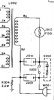
Here is the schematic from the SM for the power switch section.
The switch tests ok, when open O.L when closed 0ohm. The only other thing that I can see that could cause this symptom is G001 misbehaving. The SM describes G001 as a printed comp. 0.1 uF/120 ohm. I read O.L between the G001 leads in circuit. What is the best way to test G001?


2010 power switch circuit.jpg
IMG_20170227_101925.jpg
 
It's not your issue. You need to measure for AC voltage at the power transformer secondaries next. Basically the tree sets of paired wires shown at the left side of the schematic snippet you posted. Yellow, red and green wires.

A 75W DBT bulb on a 2010 may not even produce any light. The lowest wattage you can find would be better, like a 15W.
 
It's not your issue. You need to measure for AC voltage at the power transformer secondaries next. Basically the tree sets of paired wires shown at the left side of the schematic snippet you posted. Yellow, red and green wires.

A 75W DBT bulb on a 2010 may not even produce any light. The lowest wattage you can find would be better, like a 15W.

rBuckner.... Thanks for the guidance on where to go next. I appreciate everyone's input.....

The lowest wattage incandescent I have is a 25Watt. I tested with my 2245 and it lights and then dims correctly. Tried on the 2010 and nothing.
I will be measuring the transformer secondaries next and will update with measurements as soon as I can.

I did expect that G001 is not the cause of the unit not powering on. I was just trying to figure out why the switched outlet is always on. I was thinking that starting as far upstream as possible to make it correct and work my way downstream....
 
Not a bad idea really. If that part were shorted the outlet would always be "on" and I'd bet that any load on it would soon make G001 go open. You could unsolder one side of G001 temporarily to see if that was it or welded switch contacts but connect something like a lamp to the switched outlet first to see if it is really well connected. My hope is that your power switch is actually bad as that can be replaced. The power transformer... not so easily.
 
Not a bad idea really. If that part were shorted the outlet would always be "on" and I'd bet that any load on it would soon make G001 go open. You could unsolder one side of G001 temporarily to see if that was it or welded switch contacts but connect something like a lamp to the switched outlet first to see if it is really well connected. My hope is that your power switch is actually bad as that can be replaced. The power transformer... not so easily.

So I looked around for a lamp with two prong plug... Ha, the only one I had had a wider plug on one side so it goes in the newer outlets the right way. So no lamps to plug in.

I did decide to test with my 2245 since the plug would fit.
Plugged 2010 into the DBT and the 2245 into the unswitched outlet. The DBT performed as expected when the 2245 powered on.
Next I tried the switched outlet. The switched outlet performed as expected. The 2245 turned on when switch was on, and shut off when switched off... strange. I guess that is a good thing...

Now on to testing the power transformer secondaries....
 
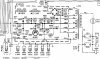
Here is the P800 schematic.
2010 p800 schematic.jpg

I disconnected J803 to remove downstream influence possible shorts.
Measure between J803 and J804. I get about 1.5V. It drops to .5V if I touch the chassis.

What is the best way to test the transformer secondaries. Do I need to detach them from the circuit and test continuity? Or measure voltage between the Green wires/red wires/yellow wires?
 
With the meter in AC volts mode for sure while under power and as you describe between similar colored wires. Get it off of the DBT to measure.

Yes, you can use the ohms mode with power off. You will not need to detach the wires.

There are some DC voltages listed at the left side, are you getting anything here?
 
With the meter in AC volts mode for sure while under power and as you describe between similar colored wires. Get it off of the DBT to measure.

Yes, you can use the ohms mode with power off. You will not need to detach the wires.

There are some DC voltages listed at the left side, are you getting anything here?

So with power off I tested the resistance as follows:
Green-Green = .2 ohm
Yellow - Yellow = 1 ohm
Red-Red = 12.9ohm
Red-Black= 6.8 ohm
other Red - Black = 6.9 ohm

With unit off DBT and powered on. There is no AC voltages on measuring green-green, yellow-yellow, etc. I confirmed that there is 123VAC on the power switch and primary.
There is no DC voltage that I can tell between any of the P800 Jumpers and Chassis. I measure between J803 and J804. I get about 1.5V. It drops to .5V if I touch the chassis. So not sure if this is induction voltage of some sort or the meter adding something when reading.

I am thinking of testing all the H802 - H808 diodes next. I have some UF4005 which I think is a replacement for W06B and the S-1.5-01 diodes. I may switch them out if they test bad.

I am getting the feeling something may be wrong with the power transformer.....
 
So I disconnected the power transformer from the P800 board. I still get no voltage out of any of the matching color wires.
Trying to figure this out. When I measure the resistance on the primary winding it measures O.L. This makes me believe that there might be a broken winding on the primary.
Thoughts?
Should I start looking for a transformer?
 
Some transformers have a thermal fuse inside that goes bad. I've heard of some that have opened up the cases, found the fuse and replaced it. I haven't but applaud the successful surgeries. It could be there is none and it's just bad (open primary) as it appears it is. Bummer!
 
Some transformers have a thermal fuse inside that goes bad. I've heard of some that have opened up the cases, found the fuse and replaced it. I haven't but applaud the successful surgeries. It could be there is none and it's just bad (open primary) as it appears it is. Bummer!

Last night I had opened up the transformer hoping to find a thermal fuse. I didn't see one so I closed it all up and went to plan B. I searched eBay for a replacement. There was only one listing for a 2010 transformer. The seller describe it as tested good. It's not as nice cosmetically, but I can transfer the cover from my existing one. Now I wait for it to arrive...
 
Back
Top Bottom