

You are using an out of date browser. It may not display this or other websites correctly.
You should upgrade or use an alternative browser.
You should upgrade or use an alternative browser.
Marantz 2010 project won't power on, need help troubleshooting
- Thread starter Aaron99
- Start date

Beamer302
Active Member
I have used an electric fence transformer to "weld" the broken wire in a coil back together . It works most of the time believe it or not. When I was heavy into antique radios I would "fix" the voice coil with this technique . Before that I would unwind the coil for about a week to find the break . That got old so I came up with this repair trick . Don't get zapped . Glad you found a replacement transformer so fast.

Aaron99
Active Member
Wow, you were lucky to find one right away! Fingers are crossed for the replacement to be good.
Received replacement transformer today. It sure looked ugly. I tested it by plugging in the primaries and testing the voltages between the same colored wires. This transformer actually produced voltages....
Since it was so ugly, I decided to take the cover off and sand and paint the center. Also, the covers that were on the broken transformer were much nicer. So I swapped them.
Before ->


Covers off, taped and being painted. I used Rustoleum Satin Black spray paint. It seems to be the correct sheen and color.
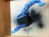
Covers from the broken one ready for installation on the new transformer.
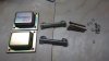
After swapping the covers and mounting brackets. Broken one on left, replacement on right.
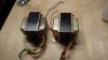
Last edited:
Aaron99
Active Member
Installed transformer into 2010. The primary leads were not long enough to connect so I spliced the wire using solder and heatshrink.
I soldered the transformer to the P800 power supply board to the appropriate jumpers.
I kept J803 disconnected. This powers up the main capacitor and the P600 board.
Plugged into the dim bulb testor. Powered on and the light bulb did not light. Which I did expect since I disconnected J803. The units lights came on.... Yay!
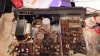
I measured voltages on the P800 board.
Then I removed the DBT and plugged into main power and remeasured.
Is J801 to high? Is J803 to low? If everything is working right and J803 is connected, I would expect the voltage to drop even more.
Location|Spec | DBT V | No DBT V
J801 ___| 14V | 14.97V| 15V
J802 ___| 34V | 32.4 V| 33.8V
J803 ___|43.5V| 34.6V | 36.3V
I soldered the transformer to the P800 power supply board to the appropriate jumpers.
I kept J803 disconnected. This powers up the main capacitor and the P600 board.
Plugged into the dim bulb testor. Powered on and the light bulb did not light. Which I did expect since I disconnected J803. The units lights came on.... Yay!
I measured voltages on the P800 board.
Then I removed the DBT and plugged into main power and remeasured.
Is J801 to high? Is J803 to low? If everything is working right and J803 is connected, I would expect the voltage to drop even more.
Location|Spec | DBT V | No DBT V
J801 ___| 14V | 14.97V| 15V
J802 ___| 34V | 32.4 V| 33.8V
J803 ___|43.5V| 34.6V | 36.3V
Attachments
Aaron99
Active Member
So where I am running into the problem is when I reconnect J803.
I plug into the DBT and the lightbulb lights up and barely dims the 25Watt incandescent bulb. I only kept it on a few seconds and measured the voltage at J803, and it was down to 6V, the front lights on the unit do not light up.
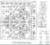
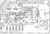
Seems like there is a short somewhere. I attached the schematics for the P600 and P800 board.
There were some hot spots on the P600 board and resistors had been replaced.
How should I go about tracing this down? Should I start with removing and testing the output transistors, and working back to the power supply?
I plug into the DBT and the lightbulb lights up and barely dims the 25Watt incandescent bulb. I only kept it on a few seconds and measured the voltage at J803, and it was down to 6V, the front lights on the unit do not light up.
Seems like there is a short somewhere. I attached the schematics for the P600 and P800 board.
There were some hot spots on the P600 board and resistors had been replaced.
How should I go about tracing this down? Should I start with removing and testing the output transistors, and working back to the power supply?
Attachments

KutzlerTrans
Jennie & I with Buddy and Barney.
Remove the outputs and try it on the dbt.
Aaron99
Active Member
I'm glad I found one that worked as well. I am interested in how the electric fence transformer could possibly fix the broken wire. Do you just hook up the primary winding leads to the electric fence transformer? Well, since I do not have an electric fence transformer I probably can't fix up the broken transformer.I have used an electric fence transformer to "weld" the broken wire in a coil back together . It works most of the time believe it or not. When I was heavy into antique radios I would "fix" the voice coil with this technique . Before that I would unwind the coil for about a week to find the break . That got old so I came up with this repair trick . Don't get zapped . Glad you found a replacement transformer so fast.
<sarc>Although there are electric fences not more than a few miles from me.... After dark I could just run out there and hookup a wire to their fence... I will try not to get caught. Or zapped....lol. </sarc>
Beamer302
Active Member
I would just hook one side of zapper to a coil. The other side of coil and other lead from fence zapper would act as a switch "momentary" I would just tap the leads of the "switch" for a half a second. The break somewhere inside the coil would arc... and or "weld" it's self together. Turn off power and use an ohm meter to test for continuity. If good your done. If not zap again. Do not zap too long !! (leave switch on for more than a half second) you will just burn up the wire where the break is and the wires will become too far from each other to arc and form a "weld". It worked for me most of the time.I'm glad I found one that worked as well. I am interested in how the electric fence transformer could possibly fix the broken wire. Do you just hook up the primary winding leads to the electric fence transformer? Well, since I do not have an electric fence transformer I probably can't fix up the broken transformer.
<sarc>Although there are electric fences not more than a few miles from me.... After dark I could just run out there and hookup a wire to their fence... I will try not to get caught. Or zapped....lol. </sarc>
Aaron99
Active Member
I'm going to remember that tip in case I ever run across a transformer that I can not find a replacement for....I would just hook one side of zapper to a coil. The other side of coil and other lead from fence zapper would act as a switch "momentary" I would just tap the leads of the "switch" for a half a second. The break somewhere inside the coil would arc... and or "weld" it's self together. Turn off power and use an ohm meter to test for continuity. If good your done. If not zap again. Do not zap too long !! (leave switch on for more than a half second) you will just burn up the wire where the break is and the wires will become too far from each other to arc and form a "weld". It worked for me most of the time.
Aaron99
Active Member
Unsoldered and tested the output transistors. H004 appears bad.
Red-Blk | H001 | H002 | H003 | H004
__B-E __|0.529V|0.522V|0.502V|0.460V
__B-C __|0.521V|0.515V|0.505V|0.460V
__C-E __|_O.L__|_O.L__|_O.L__|0V
__E-B__ |_O.L__|_O.L__|_O.L__|0V
With H004 disconnected, J803 reconnected, the unit on a DBT. The DBT bulb lights up and dims, but not all the way. The lights on the Marantz are very dim. I plugged a small test speaker in and was able to get some music playing through on left channel. Only tested for a couple seconds at very low volume as I didn't want to blow anything up.
The output voltages on the power supply board.
Test1: DBT, J803 disconnected
Test2: No DBT J803 disconnected
Test3: DBT, J803 connected, H004 disconnected
Location|Spec | Test1 | Test2 | Test3
J801 ___| 14V | 14.97V| 15.0V | 14.28V
J802 ___| 34V | 32.4 V| 33.8V | 23 V
J803 ___|43.5V| 34.6V | 36.3V | 30 V
J812 ___| 6.4V|no test|no test| 3.94V
Red-Blk | H001 | H002 | H003 | H004
__B-E __|0.529V|0.522V|0.502V|0.460V
__B-C __|0.521V|0.515V|0.505V|0.460V
__C-E __|_O.L__|_O.L__|_O.L__|0V
__E-B__ |_O.L__|_O.L__|_O.L__|0V
With H004 disconnected, J803 reconnected, the unit on a DBT. The DBT bulb lights up and dims, but not all the way. The lights on the Marantz are very dim. I plugged a small test speaker in and was able to get some music playing through on left channel. Only tested for a couple seconds at very low volume as I didn't want to blow anything up.
The output voltages on the power supply board.
Test1: DBT, J803 disconnected
Test2: No DBT J803 disconnected
Test3: DBT, J803 connected, H004 disconnected
Location|Spec | Test1 | Test2 | Test3
J801 ___| 14V | 14.97V| 15.0V | 14.28V
J802 ___| 34V | 32.4 V| 33.8V | 23 V
J803 ___|43.5V| 34.6V | 36.3V | 30 V
J812 ___| 6.4V|no test|no test| 3.94V
Aaron99
Active Member
So I am looking for the replacement output transistor 2SD315.
It uses what I believe are TO-66.
I have read elsewhere on AK that MJE15032G is a substitute.
They seem to be readily available in TO-220. So is that what is done, use the TO-220 style on the heatsink?
Also, do I need to do both H003 and H004 at the same time? Is this what is meant by matching pairs? Or do they need to be measured to find a match? If I order 10 should I be able to match enough to replace all 4 outputs, since I don't want to only do half of them. My OCD in making it look symmetrical would force me to replace all 4 of them.
It uses what I believe are TO-66.
I have read elsewhere on AK that MJE15032G is a substitute.
They seem to be readily available in TO-220. So is that what is done, use the TO-220 style on the heatsink?
Also, do I need to do both H003 and H004 at the same time? Is this what is meant by matching pairs? Or do they need to be measured to find a match? If I order 10 should I be able to match enough to replace all 4 outputs, since I don't want to only do half of them. My OCD in making it look symmetrical would force me to replace all 4 of them.
KutzlerTrans
Jennie & I with Buddy and Barney.
Matching the bigger transistors is not as nessesary as nipping it in the bud at the beguining of the amp.
Aaron99
Active Member
Recapped the P600 board last weekend.

Replacement transistor arrived today. New old stock 2SD315 in original bag.
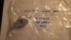
Installed, and it sounds good on aux and tape setting.

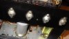
Now on to troubleshoot why the FM is not working.
AM works fine, all other inputs sound good. FM has no sound, the signal strength meter does not move when in FM, it moves in AM.
Replacement transistor arrived today. New old stock 2SD315 in original bag.
Installed, and it sounds good on aux and tape setting.
Now on to troubleshoot why the FM is not working.
AM works fine, all other inputs sound good. FM has no sound, the signal strength meter does not move when in FM, it moves in AM.

Aaron99
Active Member
Wow, a lot of progress made! Good work Aaron.
Yes, I am happy that the 2010 is now working. It feels like 2 steps forward and 1 step back.
I worked on the phono board P300 last night.
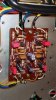
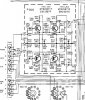
It now seems worse with humming. I checked that the ground wires are intact. But something seems worse now.I have checked that the phono board is grounded.
I replaced the following:
Location | Spec _____| replacement __| Mouser#
C301/C302| 2.2uF 25V | 2.2uF 50V film|MKS2B042201F00KSSD
C309/C310| 100uF 10V | 100uF 25V ____|UVY1E101MDD
C313/C314| 1uF 35V __| 1uF 50V film _|MKS2B041001C00KS
C315 ____| 100uF 35V | 100uF 35V ____|UPW1V101MPD
C316 ____| 47uF 50V _| 47uF 50V _____|UPS1H470MED
H301-H304| 2SC1327 __| KSC1845FTA ___|KSC1845FTA
Aaron99
Active Member
I did further testing. This time I tested listening with very good headphones. I can hear noise/hum on all settings and low/no volume. The noise is louder on the phono setting. The noise has probably been there, I was just excited before that I heard sound, and hadn't really listened carefully with headphones.
The noise is the same with the bottom cover on and off. When on Phono setting, when my had gets near the phono board, it gets quieter.
I think there is also AC ripple humming occurring from the P800 power supply board.
Measuring between J605 and ground on Amp board. I see some AC. Is this normal? I have not yet had experience trying to isolate/troubleshoot hum.
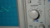
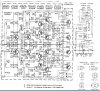
The noise is the same with the bottom cover on and off. When on Phono setting, when my had gets near the phono board, it gets quieter.
I think there is also AC ripple humming occurring from the P800 power supply board.
Measuring between J605 and ground on Amp board. I see some AC. Is this normal? I have not yet had experience trying to isolate/troubleshoot hum.

That is normal and not the cause of noise/hum. You suspect hum from the P800 board, did you scope it? There should be less noise than the main filter cap had on it. I'd love to have this on my bench and do some measurements with my audio analyzer! I kind of wonder, since this is a low price model, if the noise is normal. As in they cut a corner or two? That doesn't match with all I've observed of all of their models though. By far the worse engineered of the Marantz units I've seen are the 2500/2600 models. They sound good but oh man, they're horrible to work on!
