• The move to the new server is done. There are some software and database maintenance updates in process. This has us passing the hat around to help out. We appreciate any donations. Seriously, even a dollar helps. The payment page may be found here - https://www.audiokarma.org/support.html

Marantz 2215 hiss and hum

Thanks, I was thinking of using the WIMA film caps for the lower-capacitance caps.
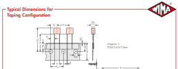
When ordering WIMA film caps, I believe the bulk caps have short leads so you probably want to order the tape/reel packaging which has longer leads (if available). It might be easier to install. Mouser might have a larger selection and you should be able to order small quantities. Sometimes Digikey does not have stock on these.
1693411956978.png
 
I'm having trouble figuring out what to use for C715-7C16 (100uf 6.3V) caps. Mouser doesn't seem to have any audio-grade caps at those values. But they have several general-purpose, high-temp, low-impedance, etc. Should I choose one of those? They're wired in parallel with 100ohm resistors on the output of an NPN emitter, to ground. It doesn't appear to be on the signal path (I could be very wrong though..). Trying to remember this stuff from school, but it's very fuzzy. I think these caps are just bypass caps, so I imagine low-impedance would be good. Or maybe the opposite is true...


power_amp_section.jpg
 
Last edited:
When I do a search at Mouser.com, I get 28 results - In Stock, of various voltages. You need to measure the lead spacing and diameter for the existing caps to see what will fit the board. You can use a higher voltage rating, but keep the capacitance value. If you are trying to keep with "Audio Grade" caps, they do have Nichicon FG (which are being discontinued but in stock that are good. If you need help, let me know. Use this link to see my search.

https://www.mouser.com/c/passive-components/capacitors/aluminum-electrolytic-capacitors/aluminum-electrolytic-capacitors-radial-leaded/?capacitance=100 uF&product=Audio Grade Electrolytic Capacitors&termination style=Radial&instock=y

EDIT: I also attached a guide to Nichicon capacitors, it's a little outdated since they have been slowly discontinuing their products, but it will give you a feel for the differences.

Most (if not all) are for audio use. See below.
1693415804355.png


1693415172224.png
 

Attachments

Last edited:
Thanks! Yeah, I meant there were none rated at 6.3V. If a higher voltage is always ok, then that solves the issue. I do wonder why they chose 6.3V in the first place though. Maybe just cheaper?

I haven't removed the board from the chassis yet, and I don't think I want to yet (I don't yet have a good place set up where I can keep the the amp parts organized and away from cats and kids, but will soon), but it looks like they're either 3.5mm or 5mm lead spacing.

I don't necessarily need to keep with "audio grade" caps. I don't know what difference it actually makes.
 
The manufacturer probably originally chose lower voltage parts for either cost or board space reasons.

When you do go to replace the electrolytic caps, do these things:
  1. Take photos of the board for reference, in case you forget the orientation of the cap +/-.
  2. Take a sharpie marker and mark a dot on the top of the cap that faces the front of the receiver. This is so if you forget the orientation of the old cap you can reference the mark. You can also tell if you missed replacing any caps.
  3. Sometimes the board markings for '+' are not always correct. Make note of any that seem to be in the wrong orientation and replace the new caps in the same orientation. That's where #1 and #2 become important.
  4. Replace one cap at a time. Remove the old cap and any old solder. Use a solder sucker or braid to remove solder. Clean-off the solder pads with isopropyl alcohol. Solder in the new part. Use flux if you need it for a clean solder joint.
  5. Do one board at a time, then test. This way if there is a problem, you know which board you worked on and can isolate the problem. If you do them all at once is becomes more difficult to find and isolate the problem.
  6. Move any wires out of the way, use tape to pull it aside if needed. I've melted wire insulation by accidently touching a wire in the way when soldering a part in.
 
Thanks dankik, these are great tips, and I'll follow them. Taping the wires to keep them out of the way is one I hadn't thought of. I do have a couple melted spots on my soldering iron cord.
 
I've ordered parts for the power supply board and power amp board, as well as a cheap component tester (for the price, it's worth a try I think, and my main use will be to determine if transistors have matching hFE values, so hopefully it can at least do that) and components to build a dim-bulb tester.
 
One last thing, when you go to replace transistors... take note of the EBC leads of the new replacement transistor. Sometimes the replacements have the leads in a different order or there are multiple package configurations base on P/N suffix. Your transistor tester should be able to verify the leads.
 
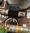
I was about to order parts for the phono board and tone board, but noticed the phono board has a transistor listed as "2SC 458LGA (B)". Looking at the phono recap kit from peace.love.and.music AKA Affinity for Artifacts uses a KSC1845FTA and says it's the "correct replacement". However, @MarantzRefrb uses the KSC1815FTA as a replacement for this and some transistors on the tone amp board.
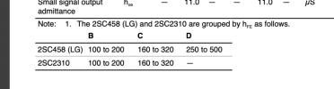
What I don't get is -- what is a 2SC458LGA (B)? I only see this transistor listed as 2SC458LG with variations "B", "C", and "D". Is "2SC458LGA (B)" just the "B" version?

If so, it appears that the small signal hFE is 100-200, which his closer to the KSC1815FTA than the KSC1845FTA, if I'm reading things right.


Screenshot 2023-09-12 at 12.41.36 PM.png


Screenshot 2023-09-12 at 1.03.06 PM.png Screenshot 2023-09-12 at 1.04.48 PM.png
 
Last edited:
I followed the hfe gain range as closely as I could with my transistor replacements, and according to the Service Manual.

Since, it's been reported elsewhere that the Phono board can oscillate if the 1845 was used, the recommendation was then to use the 1815.
 
I followed the hfe gain range as closely as I could with my transistor replacements, and according to the Service Manual.

Since, it's been reported elsewhere that the Phono board can oscillate if the 1845 was used, the recommendation was then to use the 1815.
Thanks! That settles it then.

But do you know if the "2SC 458LGA (B)" listed in the service manual is the same as "2SC458 (LG) B" in the data sheet?
 
I managed to break the lead on one of the varistors (SV-3A) on the power amp board. I've looked at some other threads about this (e.g. https://www.audiokarma.org/forums/i...rantz-2230-rebuild.565518/page-2#post-7487111), and it sounds like they're very difficult to find, so people either try to grind the case back a bit so they can re-solder, or they figure out some combination of diodes that approximates the varistor.

These threads are pretty old though, so I'm wondering if there are decent replacements available now.

Screenshot 2023-09-13 at 7.47.47 PM.png
 
I got a Dremel and was able to repair the SV-3A (added some JB-Weld as well).

I discovered this broken varistor after powering up the receiver for the first time after re-working the power amp board. Glad I had a dim-bulb tester, because the bulb lit right up. I'm hoping this bad varistor was the cause, or perhaps the lead was touching the heat sink. I'm not totally sure what the varistor does in this circuit though.
 
Thanks! That settles it then.

But do you know if the "2SC 458LGA (B)" listed in the service manual is the same as "2SC458 (LG) B" in the data sheet?

The parts list I made should show the exact transistor replacement I used in a specific location, it's been years since I worked on the 2215's though, hard to recall.

I got a Dremel and was able to repair the SV-3A (added some JB-Weld as well).

I discovered this broken varistor after powering up the receiver for the first time after re-working the power amp board. Glad I had a dim-bulb tester, because the bulb lit right up. I'm hoping this bad varistor was the cause, or perhaps the lead was touching the heat sink. I'm not totally sure what the varistor does in this circuit though.
That's a heat sensor that rides on the heatsink, it changes the bias voltage if the amp is getting too hot, by lowering it.

That's why they say when setting your bias, let it idle with the volume all they way down and no signal going through the amp, wait 15 minutes, then set the trimmers. All to do with heat.
 
The parts list I made should show the exact transistor replacement I used in a specific location, it's been years since I worked on the 2215's though, hard to recall.


That's a heat sensor that rides on the heatsink, it changes the bias voltage if the amp is getting too hot, by lowering it.

That's why they say when setting your bias, let it idle with the volume all they way down and no signal going through the amp, wait 15 minutes, then set the trimmers. All to do with heat.
I see, thanks!
 
@MarantzRefrb - did you ever find out if you can adjust the DC Balance without an oscilloscope on the 2215? I see in your thread that you were asking about it, but then were able to get an oscilloscope.
 
When I looked at the clipping on my scope, the L&R channels were perfectly balanced. When I replaced the trimmers in that location, I measured the resistance set on the old trimmer, and set the new trimmers to the same value as the old ones, and soldered it in. It was as if nothing had changed.
 
Back
Top Bottom