

You are using an out of date browser. It may not display this or other websites correctly.
You should upgrade or use an alternative browser.
You should upgrade or use an alternative browser.
Here are the parts I used:I can' tell from the photo, but did you verify that the replacement transistors are installed with the correct leads connected. Some look like they are twisted to install. Please list the H# and replacement transistor for each that you changed. I apologize if you already listed it earlier in the thread.
View attachment 2985798
| Part ID | Service Manual | Replacement Value | Replacement Brand | Replacement PN | Mouser Link |
| H701-H702 | 2SC945 | KSC945 | ON-Semi | KSC945YBU | KSC945YBU |
| H703-H704 | 2SC853 | BD139 | ON-Semi | BD139 | BD13910STU |
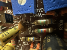
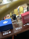
Photos of the transistors on the power amp board attached.
Attachments
-
 tempImageG8v84w.png852.7 KB · Views: 10
-
 tempImageNTO83D.png1,003.1 KB · Views: 10
-
 tempImagejhucJj.png937.8 KB · Views: 10
-
 tempImageVNCVft.png936.7 KB · Views: 9
-
 tempImageY8pWAi.png792.7 KB · Views: 10
-
 tempImageCMvA2m.png813.6 KB · Views: 10
-
 tempImagekyK3uu.png663.2 KB · Views: 9
-
 Screenshot 2023-09-15 at 10.24.07 AM.png654.5 KB · Views: 8
-
 Screenshot 2023-09-15 at 10.23.51 AM.png682.7 KB · Views: 10
Oh.. I didn't even think about the suffix when ordering. Thanks!Looks like parts were installed correctly from what I can see in the photos. Could have ordered the C suffix to get the matching ECB pin out. Thanks.

When I recapped my receiver (52W), I started testing using a 40W bulb then went to a 60W bulb, so a 60W should be fine. Normally, it should glow bright for the first 3-4 seconds then dim down to a low glow. So, to answer your question, YES... you probably have a short somewhere.
Thanks! I guess I'm not sure what the next step is. Maybe I need to assume I broke something in another part of the receiver while working on the power amp board.When I recapped my receiver (52W), I started testing using a 40W bulb then went to a 60W bulb, so a 60W should be fine. Normally, it should glow bright for the first 3-4 seconds then dim down to a low glow. So, to answer your question, YES... you probably have a short somewhere.
After applying power with the DBT in place, the C703 and C704 caps have a charge. They're the only ones I tested because they're the only ones I can easily reach without disconnecting the board from the heat sink. This seems to imply that the short is somewhere past this point in the circuit, but I'm not sure about that.
Can you verify the installed polarity of caps C711, C712. (See diagram below) i don't know if it's your particular board or not, but the SM of C712 shows + 'UP' on the diagram and your photo seems to have a + on the silk screen towards the bottom. C711 & C712 seem to be oriented 90 deg different than the diagram? The schematic shows that the (-) should be connected to the base of H703/H704.
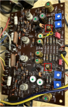
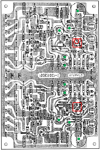


I verified with a DMM that the negative side of the C711/C712 caps are connected to the bases of H703/H704.Can you verify the installed polarity of caps C711, C712. (See diagram below) i don't know if it's your particular board or not, but the SM of C712 shows + 'UP' on the diagram and your photo seems to have a + on the silk screen towards the bottom. C711 & C712 seem to be oriented 90 deg different than the diagram? The schematic shows that the (-) should be connected to the base of H703/H704.
I also turned on the power with the DBT in place very briefly, and then measured DC voltage from each J pin to ground. The only ones that were essentially 0V were:
- J701, 702, 703, 704 (J701 and J702 have 0.47uF caps between them and ground, and 702/704 are ground)
- and J719, 720, 721, 722, 723, 724, 725, and 726 (723-726 are ground, 721 and 722 have no capacitors between them and ground, and 719/720 have 0.1uF caps between them and ground).
I'm not sure why J717 and J718 would have a voltage reading (about 2.1 V immediately after turning off the power).
Last edited:
Well, I just made a dumb mistake that might actually help troubleshoot this. I accidentally plugged the receiver into the wall outlet directly, thinking it was my de-soldering iron (d'oh). I didn't notice for about 20 seconds. Nothing smoked or exploded, but the heat sink did get pretty hot in that amount of time.
Maybe that's a clue..
Maybe that's a clue..

