You are using an out of date browser. It may not display this or other websites correctly.
You should upgrade or use an alternative browser.
You should upgrade or use an alternative browser.
Marantz 2220B problem.
- Thread starter Jermy69
- Start date

Jermy69
Member
With a lifted pad like that, here's the best way to fix it. Solder a small solid piece of copper wire across the leads. See pic.View attachment 2061083
That is a good suggestion. But I've already tried that too.

Sci85
Active Member
.
& just out of curiosity, why are y'all saying to test those when they don't affect the sound?
I mean, I get what they do...kind of.
But since that's obviously not the issue I was just wondering about that
These do affect the workings of the unit. You may not "hear" any change necessarily unless they are way off, but those trimmers set what's known as DC offset. Speakers don't work on DC they operate on AC voltage. Those trimmers set the amount of allowable DC going out the speaker terminals and you want as little as possible, ideally 0mVDC,in most cases. When the DC offset is poor, like 50mV or more, it can give an indication of something not operating properly within the unit if you are unable to get the DC offset to match what the service manual says it should be. Check youtube for setting DC offset and you'll get quite a few hits showing how to do it. After working on the unit, you should always reset the DC offset to factory spec and if it won't, you still have work to do. Good luck!
Sci85
Active Member
That is a good suggestion. But I've already tried that too.
Clean the component pins with some good cleaner. Make sure you have your soldering iron set to the correct heat, using a good 60/40 solder with flux. Never not had one stick when prepped properly.

catrafter
Marantz Specialist

Steven Tate
CEO Flat Forehead Soc.
Any time you change components, DC offset and Bias need to be checked and touched up. The new components might change those values. Like I said, if they are not near spec, bad things can happen even if you can't hear a change. It is not about the audio signal. It is about balance in the electrical circuit. You can't hear that. Of course, if it is wildly out of spec, you will hear a difference. But at that point, you are close to damaging something..
& just out of curiosity, why are y'all saying to test those when they don't affect the sound?
I mean, I get what they do...kind of.
But since that's obviously not the issue I was just wondering about that
Jermy69
Member
Any time you change components, DC offset and Bias need to be checked and touched up. The new components might change those values. Like I said, if they are not near spec, bad things can happen even if you can't hear a change. It is not about the audio signal. It is about balance in the electrical circuit. You can't hear that. Of course, if it is wildly out of spec, you will hear a difference. But at that point, you are close to damaging something.
I gotcha.
I'll look into that. But right now fixing the audio in the left channel is top priority.

So I'm thinking if it's not the C705 capacitor and not the connections to it then it must be related to something else.
What did you change just before C705?
What did you change just before C705?
Jermy69
Member
So I'm thinking if it's not the C705 capacitor and not the connections to it then it must be related to something else.
What did you change just before C705?
Part of the P300 boars. Only part because I didn't have all the correct caps. I just used what I was sent & the ones I didn't have replacements for are still on the board.
I don't remember if I explained thjs already, but I did a board or two per day & would hook everything back up when I was done...because I use this reciever literally every day.
I just did a few parts at a time on the P700 board though because of how difficult that one is (& I saved it for last.)
Hey y'all...
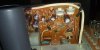
I'll take some pictures tomorrow of the P700 board & post them here.
Is there anything else y'all wanna know that might help?
Which other parts on the P700 board were swapped? We should check those as well. Sometimes issues appear after a while.
To find the issue when there's nothing visual giving us a clue usually involves measuring with the multi-meter to compare the left and right side until we find a difference between the two.
It looks like there are no reference voltage values in the Service Manual for the 2220B so we have to compare.
Does anyone have a circuit diagram for the 2220B P700 board? Would make it much easier ...


petehall347
the brandy coffee man
something happened for sure when you changed that cap . you proved it wasn't the cap itself .something changed . there are variables in play here . without you knowing how the circuits work its going to be some work teaching you all about it and you reading up and studying schematics and learning at least how to use your meter . i suggest you take break for now and study things. not being nasty or nothing we have all had to learn stuff after breaking it . i was lucky and started at an early age
Jermy69
Member
Which other parts on the P700 board were swapped? We should check those as well. Sometimes issues appear after a while.
To find the issue when there's nothing visual giving us a clue usually involves measuring with the multi-meter to compare the left and right side until we find a difference between the two.
It looks like there are no reference voltage values in the Service Manual for the 2220B so we have to compare.
Does anyone have a circuit diagram for the 2220B P700 board? Would make it much easier ...
All the capacitors & the two diodes at the top left & top right...or near there.
That's it.
The diodes were changed out after I discovered this problem.
That's all I did to it.
That's all I was given in the kit my girlfriend bought other than the speaker relay & I haven't even tried that yet.
Jermy69
Member
something happened for sure when you changed that cap . you proved it wasn't the cap itself .something changed . there are variables in play here . without you knowing how the circuits work its going to be some work teaching you all about it and you reading up and studying schematics and learning at least how to use your meter . i suggest you take break for now and study things. not being nasty or nothing we have all had to learn stuff after breaking it . i was lucky and started at an early age
Problem is I don't know where to begin.
Found the circuit diagram, C705 marked.
First measurement could be the input to the transistors H707 and H708. DC voltage should be ~ 28.2V.
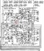
First measurement could be the input to the transistors H707 and H708. DC voltage should be ~ 28.2V.
petehall347
the brandy coffee man
the basic health check is checking the settings what you do with those white knobs regardless of the making a difference to you . first check is set your meter to read dc volts and put one probe in in each channels speakers posts as in left plus and minus then in right side . then we can move on to the idle current thingProblem is I don't know where to begin.