• The move to the new server is done. There are some software and database maintenance updates in process. This has us passing the hat around to help out. We appreciate any donations. Seriously, even a dollar helps. The payment page may be found here - https://www.audiokarma.org/support.html

Marantz 2230 Gift, for whom?

rBuckner: Hi, Thanks for getting back with me on this as I wasn't sure if one was relay.
Now I know what it is. Good to know too. I have a good time with my little girl.

Take care of ol' Angus there...I love labs, and I miss mine chocolates terribly.
Spot 18.5 years and Wanda 14.5 years. They were great well trained
bird dogs. They had wonderful lives in the water and out.

To bore you with Lab stuff:

I used Richard A. Wolters books as a guide. Bird Dog, Water Dog, Game Dog.
Funny I used to take the dogs out with me and was talking with some dog training
lady who proclaimed that yes those work but are dated...and suggested that I
use clicker training to really train them well.

Two things I took away from his books:
1. Tested his statement, lab would rather retrieve then eat. TRUE
2. Early exposure and training have life long benefits. TRUE
2a. It's the same with children too. Early exposure and training/education
kids perform at a higher level academically, socially all their lives, better adjusted,
more activities, less problems, etc.

hofferwood, Chuck: I saw that, but for some reason I had brain flatulation
and it didn't quite register with me. I got it now, the 1 was farther away and I
didn't put it with the rest of the numbers, kept thinking 97, how can that be.

--Spike
 
We love labs! First two were sisters, a black and a chocolate. Then a yellow rescue lab - our best dog ever! Then took over Angus at age 7 due to skin allergies where he lived. Wonderful ole fella. :D

Our first black lab was a nut about playing fetch. I once tried to see how long she would go. After an hour my arm was falling off and I gave up. That round went to Kerrie!

BTW - Marines have my deep respect - thanks for serving, you are appreciated!!
 
Still in research and parts acquisition.

The question of vellum vs milky white Mylar.
I've got to go back to the vellum thread and read up on it again. LINK
I didn't take notes. Or put them somewhere and I'm not sure where.
Choices are as follows around post #101:
White translucent 48lb Vellum card stock - favorable reviews, 10 sheets $4.95
25 sheets of 0.005 "dura lar" film. $18
1 sheet Hobby Lobby - $.50 Passed by today but forgot to check it out. vellum or Mylar.
Double Sided Adhesive Tape Kaisiking 5mm / 10mm x 25M Heat Resistant High Adhesion Transparent Acrylic Tape $9.99

So I'll put the resources here to remember them.

In spite of buying the cap kit from patfont, I had to order caps
because I didin't know and assumed it came with all the caps
for the 2230 receiver. NOT.

Not happy and pat offered to take the kit back.
Time is valuable, especially on a first one of these.

Still it was 39 capacitors short that I was expecting though.
Not happy to have to spend more time ordering caps,
Checking lead spacing etc. So for just about every I trying to
narrow it down to 5mm lead spacing for the following:
P150 AM Tuner Board
P300 MPX Decoder Board
P500 FM detector Board
P550 Muting Board

Lots of UKLs that MBura had listed.
I assume the low leakage are beneficial in these
boards for better function.

The one thing I did though was pay a little extra
for the 105*C UKLs. If I recall they have better
rubber seals, maybe a bit more electrolyte
and more secure leads, as said by a famed
engineer and capacitor designer. Any way,
they should last longer then the 2000 hour 85*C
when used in the same location.

Some other slight changes I wanted were also
different then the standard wima metalized line.

Where they were available,
I used the small Nichicon
Mylar and Aluminum foil caps.
No wiggeling inside the cap
as there is with metalized foils.
My description of the phenomena
for Everyman.

Kemet PolyPropStacked Caps.
Check against some old inventory of
Panasonic ECQs that aren't made any longer.

We are living in a great time for doing this
sort of thing with all the information and good
parts available...while they last. End of life
parts is now more of a reality than we realize.
More and more manufacturing is going cheap
break it and throw it away.

Shut eye time again.

Almost, I assume the back side of the face plate is black type silicone
that holds in the dial neutral density filter and the black o rings around
the push buttons. I was thinking of the fast dry Right Stuff silicone.
But this feels more like a stiffer black caulk.
 
Last edited:
While parts are on their way, except no one seems to have any KSC1845s
any more, unless we by 6500 at a time. LOL

So I before I start in on geting this amp refreshed upgraded etc I set about
to take some measurements. I like to figure stuff out that is why I do it,
most folks don't bother as it's time consuming and you used to need
lots of high dollar equipment. Now it's mid dollar equipment if you can
find the right stuff used.

I've taken some pics and won't have them posted until the lab
sends them to me. I'll have a write up about it too.

Here's the short version though.

1kHz @ 1V in, (distortion at -113dB)
Right Channel 7.5 Ohm load: 51.8V before clipping. THD -70dB.
Left Channel 5.3 Ohm load: 46.1V before clipping. THD -57dB.

Don't even ask.

So now, I'll keep the same set up when the receiver is "new" and
after the burn in period. If the process changes then nothing is valid,
but as long as right channel hardware is same
and left channel hardware is the same, the measuring process is valid.
For my use.

For some reason in this 50 year old 2230, 3rd harmonics have way more
distortion artifacts then 2nd harmonics.

For example at 1kHz, it's
F = -48.5 dB
2 = -57 dB
3 =-52 dB much worse, it should be lower than 2nd harmonic, like -67dB.

It's like this for other frequencies measured also.

I contemplate that at 50 years old, the circuits don't function properly any longer
as capacitors are dried up and barely working throwing everything off. Lets us not
forget the 2sc458s along with drifting other parts.

After restoring one of these, we all need to care for the transformers in these units.
The enamel coated wire in these should be starting to break down, as they had a
40 year life expectancy. Something to file away and recall when things start to go
wrong when we think they shouldn't. At least it's not as bad as in some tube amps,
high heat, no or minimal derating, hi abuse factor if musical instrument amp.

-- Spike
 
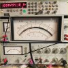
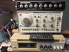
Here is the first batch of pics back from the lab. This first image is a composite image
of the HP339A oscillator, 1kHz, @ 1v output. This corresponds to 0 dB 1V
as shown in the upper right corner of the enlarged meter.
The top row of the meter is expressed in dB.
The second row, or the row just under it Volts.
The red indicator is on 0 dB and 1 Volt.

At the top is the frequency counter.
I wanted to get it as close as possible
to 1kHz. With a bit of gentle turning of
the Frequency Vernier along the bottom
row of knobs I was able to dial in
1.00029418 Hz
or
1000 & 1/3 Hz.

They are old and clunky these HP339As. And with careful
modification they can be made better then stock. The are
accurate and built like tanks. Not like the throwaway stuff today.

01.01  -1 1kHz-1V-0dB.jpg
 
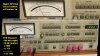
This next pic from the lab shows two composite images.
The distortion analyzer I love is the ShibaSoku Automatic
Distortion Analyzer AD725D. It's fast!

The next thing we want to do is verify the output from the HP339A
is matched by the input into the 725D. At the top you see a partial view
of the analyzer using the level function. There is a bit of parallax from
taking the pic at an angle, but it was on 1 second row which corresponds to Volts.

The Bottom view show what it looks like measuring distortion.
The middle row of buttons simplly press DIST with ANALYSIS
along with SLOW and you get to hear lots of relays switching
based on measurements until it settles in at the right side of
the long row of buttons. It describes the meter range.

In this case the HP339A oscillator output is less than:
0.001%
-100dB
10uV

Take either of those numbers from the botton and
use the meter's pointer to find the answer.

Using the red dB row, I see needle on -13.5 dB
we add that to the buttons -100 dB and it's -113.5 dB.
This give me the basis from which to analyze the Marantz 2230
in it's original form from 50 years ago.


01.01  -2 725D HP339A Output.jpg
 
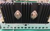
The next composite pic from the lab shows the the results of the Marantz 2230 as it is currently
before modification. The original owner replaced the output transistors a few years ago.
The are shown in the here:

01.01 -5 Output-1.jpg

This is how it should be done. Notice there is no excess heat sink compound oozing out from beyond the transistors?
That should be our goal when we replace them. No slop. It's all about attention to detail. The gentleman I bought
this amp from was a mechanical engineer at General Motors. He was a Technical Fellow at GM ensuring GM
met their emissions standards. Highly complex to say the least.

Moving right along we see the right channel measurements. From 1V in and turning up the volume knob
until it starts distorting then backing down to a nice 1kHz sine wave.
Here is that composite image:

01.01  -3 Rt Ch THD.jpg

So we're at -60 on the button, and -11 on the dB meter scale for -71 dB THD from the right channel.

Lets take a look at the left channel and see how that compares:

01.01  -4 Lt Ch THD.jpg


For the left channel measurements, we start at -50 on the button and add -7.5 dB from the meter scale for -57 dB THD on the right channel.

A bit of difference between the right channel and left channel
Right Channel: -71 dB THD
Left Channel: -57 dB THD

This gives me a starting point before I work on the receiver.

Two issues cropped up that I wasn't prepared for, somehow i could not find
my box of large Dale 5.1 ohm 75 watt load resistors. I had about 10 of them.
The only I did have was one on the bench. I went through about 99 % of
my supply storage (which took well over two hours) to try and hunt them down. NO LUCK.

Then if that wasn't enough the only other reasonable resistors that I found were two 15 ohm
25 watt dales I could parallel for 7.5 ohms I tried to match those up with series resistors...
either 470 ohm 10 Watts or 6.8 ohm 10 watt.
Closest was three 6.8 ohm in series then parallel them with the 15 ohm resistors.

It still wasn't close enough so I just said EFF it, I'll have two individual channels of measurements
and won't consider them together.

Yes, I could have kept switching around the cabling with the load resistor on it. But there isn't much
room on the bench hanging out behind the receiver or turning it backwards but reaching to the turn the
volume knob.

Once I got this two key measurements I thought it would be a simple matter now
of doing some square wave measurements, at 50 Hz 10kHz and 20kHz. That would
give me a good indication of the state of the receiver. This is discussed in the
Tek Cookbook of Standard Audio Tests, page 15.

Then setting up for square wave response, I've used my Leader LFG - 1300S Function Generator
it is just fine for this type of work. Set it all up for the next batch of test and measurement
and viola. Nothing. Powered on confirmed settings more than once, and on and on
i tweaked and changed and turned dials, etc. NOTHING.

Finally I just pressed the remote button on the 2230 where i had my bench speakers
plugged into and again absolute nothing, no sound.

NUTS

I went back to Tek Cookbook, p 7 and reviewed Harmonic Distortion and Figure 18 shows
commonly used frequencies: 50,100,400,1000, 5,000, 10,000, 15,000.

Two things make this fast and easy, the HP339A keeping the voltage setting as is
and turn the knobs for each frequency.

Then on any Frequency, from the ShibaSoku 725D, take
the fundamental distortion measurement then press the button
for 2f, 3f, 4f, and record each.

Go to the next frequency, turn the HP339A knobs, take
the fundamental distribution measurement, then press the button
for 2f, 3f, 4f and record each.

Continue for the remaining frequencies, change channels and repeat.

Once finished I packed it all up made a quick post here and went to bed.
I think I'll do one other set of measurement using the 5.1 ohm 75 watt dale
on the right channel only. So they using the same cable and resistor.

Not doing it tonight though.
I'll post those results along with combining the data from Harmonic Distortion
measurements and enter data into a table for easy reading.

-- Spike
 
Last edited:
As I mentioned in the prior post I'd redo the right channel measurements using the same
Dale 5.1 Ohm Resistor I used in the left channel in the prior measurements.

Why 5.1 Ohms and not 8 Ohms you ask?
A long time ago I was advised that 8 Ohm is rarely what a speaker
measures...a more accurate load would be about 5 or 6 Ohms.

So, I happened upon a closeout that had a 10 pack of these resistors.
They are the good NH-Variety which have the Aryton-Perry winding for
lowest reactive components (it says so on the data sheets front page).
I'm pissed that I can't find the other resistors as I put them somewhere
safe, but that never seems to stop my other half from placing them in
a bag or box and putting it somewhere that is challenging to find.
I've attached the datasheet as a thumbnail for your reading pleasure.

01.04 -6 Dale Resistor.jpg

First run with different resistors:
A bit of difference between the right channel and left channel
Right Channel: -71 dB THD
Left Channel: -57 dB THD

Second run with same resistors:
Right Channel: -71.5 dB THD
Left Channel: -55.5 dB THD

The difference in channels is still apparent in the 50 year old Maranta 2230.
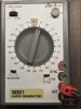
I did manage to find my portable 3001 Signal Generator from BK Precision.
I forgot that I had it, but I found it for my futile search for my other large Dale 5.1 resistors.
And of course the inconvenient failure of my Leader LFG1300s. I'll open it up at a later date.
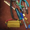
Here is the inconvenient one's pic:

01.04 -5 Leader et.al..jpg

Here is the 3001:

01.03 -1 BK 3001 AudioGenerator.jpg
 

Attachments

Last edited:
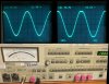
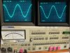
I almost forgot, here are the square wave measurements as seen by my oscilloscope.
An older model 2246 MOD1 Analog Scope. It's old and it works just fine. Though I
am looking at a modern Rigol scope.

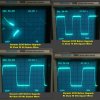
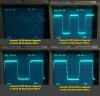
Back from the lab are the composite images of the four square wave tests that I ran
of the Right Channel and the left channel of this Marantz 2230 I'm fixing to upgrade
and give to my little girl.

Here is the right channel composite square wave image:

01.02 -1.1 Rt Channel Square Waves.jpg


Here is the left channel composite square wave image:

01.02 -2.1 Lt Channel Square Waves.jpg


What is interesting to me is that these square waves aren't bad for an unserviced 1972
Marantz 2230 except for output transistors. None of the front panel lamps work any
longer either, they are on my to do list.

Now, the low frequency response is pretty revealing that the old power supply filters
have seen their better days. They look great than 45*. Those should flatten out considerably
after the upgrade to the receiver which includes new and greater micro farad and voltage.

Then reading the Tek Cookbook (ibid.) These square waves in this sequence are as follows:
50 Hz, 10 kHz, 20kHz, 50kHz the latter two I added in there and they don't show much difference.
The rounded leading edge of the square wave should be 90*, not round.
It should have a sharp edge like the at the back of the square wave.

So, for me this will be also and interesting project, not just for my little girl,
but also as this is my first Marantz receiver to upgrade. Now that I've quantified
what I'm starting with, it will be nice to see the results.
Of course I want to hear the results too (that goes without saying).

So I have a month and a half to get this done.
I don't have a 3/8 inch chisel to peel away the old glue.
Or maybe I do back in the garage somewhere...
another day, another search for a tool I think I have.

Stay tuned.

-- Spike
 
Last edited:
I couldn't just stop there, so ate some chow and opened it up and started.

Started with desoldering the Mains filter caps before removal. And, right off the bat
melted a green wire that goes to the other side of the Receiver. Well now that I
broke the ice, as I was desoldering away I notices the mains cap wires didn't look
correct. The white wires were find, but the red wires looked the dull gray. Cold
solder joint?
I continued and then started noticing the mains filters wires weren't in such good
shape, both red and white wires that connect to the close power amp. Oh, when
the output transistors were replace, issue right there.
You know how it feels when the wire is about to break from bending to much.
Both red and white wires. And then it dawned on me that the red wire cold
solder joint connection wasn't factory made, is was and attempt at desoldering them
from the main filter.

That got me thinking about Pat Font and his recommendation of changing out those
red and white wired with TSSC 19 awg wire. I didn't have any but did find some good
old 18awg 105*C milspec, deep silver plated copper stranded wire.

The reason I was desoldering is I thought there wouldn't be enough of a serviced loop
to cut, strip, and resolder to new power supply capacitors.

By desoldering, I contaminated all the wire ends, now about and inch long, and again I remember
about Pat Font recommending changing the wire out. In for a penny in for a pound. I finally
got through pulling all the white wire though the receiver. Next up is doing the same
with the red wire, then replacing the caps I pulled with the new Nichicon Super Through capacitors.

I want to see how the amp responds to it. I've got my base line tests from which to compare.

Until next time,

-- Spike
 
Woo Who,

If I didn't know any better I'd think I'm a rookie making rookie mistakes and losing screws every time I turn around.
And then, drum roll.................
cleaning out solder balls, a couple slide down into the the special covered board in the center and hopefully
don't get lodged in the big tuning capacitor.

Installed the 2nd filter cap backwards because I took the picture upside down, and I figured it out when
Main Filter has 68 VDC and 2nd & 3rd filters had .6mV on them. It's the orange wire, yellow wire one
coming straight from the rectifier. Keyboarding this from the other room so I can't see it.

And I wanted to waterboard Square wave the the thing to see if it made a difference.
Oh the sin of being a do gooder and trying to help out the good members of AK especially
new people who might not have done nor seen some of the audio tests before.

@ patfont, the good news is I didn't unsolder the connectors you soldered on the mains filters.
That saved me mucho time and aggravation trying to find them in the automotive electrical boxes.

There is no room in the bench room for much else. And no sooner then I organize it it takes
hours, weeks, months, years to find parts that I knew where right There.

While I might not be a Jim Williams or Bob Pease, my bench looks like though. May the rest in peace.

I'll have some ugly and not so ugly pics when I get them back from the lab.
It's what happens when you ignore the book by not just clipping the leads
leaving just a little color on the terminals to ID how they go back...buy I took
pics of it and wrote it down!

If anyone was wondering why no QA401 pics etc. The Dell laptop fried after someone other
then me used it. Now it only beep Beeps. Went though basic troubleshooting and hopefully
it's just a memory card. BUT it shouldn't have failed.

Now I'm taking the 2230 outside to give it a good blow job with 60 PSI air.
 
Taking my next break, then set to the clean the amp board P800 or 850.
Oh and that lovey Effing cap and Marantz would have failed their IPC test.

Part of what we learn is how to make electronic assemblies that last AND are
serviceable. AND bending over the snap mount terminals...I'm preaching
to the choir. I'll have to scrape the trace, solder a wire running from the
trace to the new snap in terminal and back.

It's too ugly to take pics. At least I can take some of repairing this abomination!
I started out so happy so early in the morning too.

Hey patfont, how the heck did your test amp survive all those cap changes?
Did you cheat and make some boards up in China so that changing caps
would be a snap?

Stay tuned for tomorrow's hunt for the 3/8 inch scraper thing or, how else
can Spike ruin his little girls receiver before she even gets it. NAAAHHHH.
Have the fun is figgering out how to fix it.

Good night boy's and girls.
 
Not much accomplished today other than some cleaning and administrative stuff.
The pics came back from the lab so we have some interesting stuff here to discuss.
Some is not at all so good either. I feel almost ashamed to show some of these
pics.

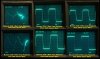
But first lets take a look at the Square Wave Testing, at 50 Hz, 10kHz, and 50khz.

01.05 -1 Right and Left Channel SquareWaves.jpg

It surprised me at how crappy the 50 Hz square waves are. I made sure that I warmed up the receiver, biased both sides:
Right (5mV)
Left (5mV) had to raise it from 3.3mV.
and verified the main voltage supplied (35.8V).

Right channel 50 Hz I thought would do better than it did. But these are just the main filters.
Left channel 50 Hz, wow, it has issues and I don't know where they come from.

As I go through the amp, I'll document each stage, then I'll show the result with these square waves.
It gives us the ability to see which board affects the outcome at these three frequencies.
I think I'm getting the process down finally.

And oh to have had the extra money to buy the HP8648 b/c/d with all the options!
To bang out the tests with a press of a button.
That and spend a year programming through the HPIB.
Or find a college kid who need some extra beer money.

No complaints really that BK 3001 works.
 
Now We get to the fun stuff.

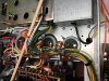
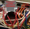
Here is what I call "The Big Ugly" I should have clipped the leads at the terminal.
I didn't think there was enough service loop, but that didn't matter, I ran new red/wht
and white wire, 18awg silver/copper teflon. I didn't feel like waiting for the TSSC wire
to come in. Sorry patfont, maybe next time when I don't mind waiting.

01.05 -2 TheBigUgly.jpg Not advertising this, you'll have to click it.

Not to be out done we have "Big-Ugly Three Amigos"

01.05 -3 Big-Ugly ThreeAmigos.jpg Same here.

And then it just came down to good practices, the next pic explains it all. Yea, I could have clipped some,
then worried as some of the leads were already short from transistor replacement. Also some wires
were so loose, I didn't want to touch them either. I'll run some more of the wire later though, I have the
blue and green for the amp driver boards and for short runs I have 20 awg orange from the rectifier, I don't
have any yellow other then smaller solids.

01.05 -4 Contamination.jpg Please click to read.

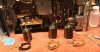
Then here are the replacements the "New Three Amigos" in the staging area ready for their new mission.
They went through their own BAMCIS

01.05 -5 NewThreeAmigos.jpg


Some things that I also feel are important as we go through this receiver we can never have
enough cleanliness either. You swabbies know what I'm talking about. Once you're ingrained
with that "Janitor in a uniform" thing it's hard to un-do it.

01.05 -6 SwabbingTheAreas.jpg


Here is a new one, for me at least, my first board removed and semi cleaned. Showing signs of heat damage.
Minor scraping getting chiselling the glue off.

01.05 -7_1 Power Amp Board Top.jpg


I'm debating on changing out the ceramics here the two 0.01uF 500 V for silver mica or for C0G/NP0 types.
At 500V I think the C0Gs are very pricey from what I recall.

Then there is that .04uF ceramic that isn't even listed in the service manual. I would imagine that is also
a 500V er.

R801, 803, 804 are gonners and listed as Solid instead of Carbon or does it mean they are
Carbon-Film?

Then the caps I got in the kit are good, but I'm just wondering if this is the right place for them, in the regulated power supply. Thoughts anyone?

How well do the Silmic IIs work here in this location?
I mean it is the regulated section of the power supply. I really like 105*C caps
and there are very good UCCs and Nichicons or Panasonics are made for this work.

Now I'm wondering if I shouldn't upgrade the two transistors while I'm in here.
The kit has the sib-01-05 upgrades in it.

I splurged and bought some 5K trimmers as 4.7K weren't available.


Ending this segment of Marantz fun and games is another ugly pic. Yes, that means you'll have to work
at it so that you can see it in all its gory detail.

01.05 -7_2 Power Amp Board Bottom.jpg You don't have to click me, really. You can see it from here.


That about wraps it up for this evening.
 
Last edited:
Not everything went like that. I didn't realize I have to more pics to share.
These are of the new wiring running along with the buddies. I call it semi finished
because I realized that I'll probably desolder some of it to gain access to the Amp Driver Boards.

Here are the "New Three Amigos" with semi finished wiring. Missing is one wrap down
where they all congregate. No telling what scuttle butt is floating around in there.

01.05 -7_3 SimiFinishedWiring.jpg


Here is the longer run to the other side of the receiver from the "New Three Amigos."

01.05 -7_4 SemiFinishedWiring.jpg


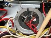
Finally, we have the space where the Regulated Power Supply Assembly.
I remembered that this was the push back wiring.
The red wire down there got snagged on something.

And the white wire from the D315 Transistor, didn't want to come off
that small area up on top. Nut's more wire to replace..but it's only a
couple of inches.

01.05 -7_5 RegulatedPower SupAssy.Removed.jpg

Okay this really wraps it up for the evening.
 
Looking good! Nice and neat. I like UPW series Nichicon on power supplies. They are 105 degree rated and just seem to do a good job under power supply stresses. Transistor replacement is a philosophy thing. I generally don’t replace them unless they test bad or are known troublemakers. If a higher power TO-220 transistor, like a D331 shows signs of heat stress, it gets replaced. And I usually replace rectifier diodes because they run under stress. But those TO-39 and TO-66 case transistors, like that C696 or D315 are always left unless they test bad. The problem is that most of those transistors have to be replaced with modern “equivalents”. Pile up a bunch of equivalents, and the circuit can function far from its original design. My philosophy for Marantz semiconductors is “less is more”.
 
Hi Steven, thanks. It's just so, want clean low noise silicon, but then Marantz was bottom of the barrel either.

Discipline, there is nothing quite like oh this will be great...and then it's not.
While I got it un wired...testing of course.
And those carbon comps have risen in value.

Also over there on the filters too the 2.2@Ohm jobs in the LR filters. But shipping on 2 or three new resistors
The L007,L008 are 3uH each. I had some low ohm resistors around here, but either too low or too high.
Plenty of 10 Ohms and I could have sworn I ordered a tape of 2.2 ohms.

Time to fix the board and get it back in the receiver.
 
I've read some posts about 2230s and something wrong with the mica caps.

I've noticed what looks like some of the caps in this 2230 look to have suffered from
heat damage in the middle of them (between the two leads) is that what they are
talking about?

or

What should I be on the look out for, how do they test?

Any info appreciated.
 
Back
Top Bottom