• The move to the new server is done. There are some software and database maintenance updates in process. This has us passing the hat around to help out. We appreciate any donations. Seriously, even a dollar helps. The payment page may be found here - https://www.audiokarma.org/support.html

Marantz 2230 Gift, for whom?

Not an expert, but my understanding is that those silver mica caps are very long lasting. I have never replaced one. But I’m sure if something in the area fails and causes a high current condition, they might fail. But they are not part of a routine recapping in most cases.
 
While I'm going though my pics, I have a question about these three ceramics and ceramics in general.
Over time these get ringy and noisy, etc. I'm wondering about C0G/NP0 replacements
for them, thoughts?

But, not on the AM/FM boards.
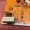
01.05 -7_1 Power Amp Board Top.jpg

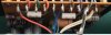
In the following pic:
Circled in red C762 this Mica cap. Now I've got some other questions
as I'm getting ready to work the amp boards:
.1 uf 20 0 WV caps, Matsushita r2X, are these the caps to keep
in circuit or change out for better caps.

White 26 numbered resistors? Are these asbestos coated that looks like paper?
What do we know about them?

01.06 Amp Board Questions.jpg


I started to pull the heat sink off one of these driver transistors, and when I started feeling
the leads bend as I rotated to remove to clean them...I stopped. They almost feel
glued on, or maybe grease that hardened and dried up on them.

Otherwise it would be desolder to pull and clean, or when the amp board is pulled,
better access to clean them.

I ask because I don't know, this is my first Marantz and y'all have done this a time or two or more.
It's a gift for my little girl so it has to last and sound great too. That's my goal.
Now w

Looks simple enough to pull the board, the red, green blue, and two whites along with
the ground strap. Not sure I can get at that screw properly, (yes I do have a couple of
90* screw heads, stashed somewhere.

That seems to be par for the course now days.
Once I start moving stuff around, it's hell trying
to figure out where I put it, in a safe place too.

Like I've been looking for the thin copper tape I bought
just to use to replace the trace pulled off the regulator board.
cut a strip 1/2 long, 1/4 wide, acetone 1/2 the adhesive off the back
Spread a dab of paste flux on the board trace, then lay it down with the cleaned copper
on the trace with the adhesive end to the terminal. Apply heat
and over the trace end and let the solder be wicked into it,
making a good everlasting joint. Then I solder the terminals
and it's good to go.

Instead, I'm running a jumper wire around the terminal
to the trace and soldered it there.

But then, I'm preaching to the choir here.

 
To each his own. I don’t disconnect the wires from the board. I remove the screw holding the ground strap, disconnect board from heat sink, remove heat sink, drop board out bottom and do my work on it there. Nothing wrong with removing the board entirely, it just makes it easy to test if I need to while working on the board. Some make elaborate wiring harnesses to make the board plug and play while working on it. That’s on my “to do some day” list.
 
While I'm going though my pics, I have a question about these three ceramics and ceramics in general.
Over time these get ringy and noisy, etc. I'm wondering about C0G/NP0 replacements
for them, thoughts?

But, not on the AM/FM boards.

View attachment 2189855...

These ceramic capacitors are to suppress rectifier switching noise, Z5U ceramic capacitors can be used here, e.g., https://www.mouser.com/ProductDetai.../S103M47Z5UN63J7R?qs=wEmTtUuRSe71jhJkulFudw==

In the following pic:
Circled in red C762 this Mica cap. Now I've got some other questions
as I'm getting ready to work the amp boards:
.1 uf 20 0 WV caps, Matsushita r2X, are these the caps to keep
in circuit or change out for better caps...

Service manual lists C762 as a mylar/polyester type. The discoloration seen may indicate heat and/or electrical stress; would replace with same film type.

White 26 numbered resistors? Are these asbestos coated that looks like paper?
What do we know about them?

View attachment 2189899...
These are wirewound resistor types, typically encapsulated in ceramic. No need to replace unless damaged.
 
index.php


If mica capacitors are 'dark colored' in the center like the one in this photo, I would probably replaced it.

Tom
 
Hi Gentlemen,

This is my third attempt to replay to everyone.

@ Steven, that is an interesting way to work on the amp boards. I'll have to find my 90* screw drivers JIS.

@ Ben, at first I saw Z5U and said what? However, what you said is correct. If I recall the
Z5u's have a 86% variance with temperature, and considering their use here and starting
with .01uF, a 100% variance with temperature would be .1uF. Still within the respectable
range for capacitors suppressing rectifier switch noise. Confirmed by the guy who writes
the Tube Amplifier Design books from the UK, I think he's on the 4th edition now.
And it would apply to the .04 uF cap as there is the 3rd diode of the four on the board.

@ Tom, I was thinking that also, the mica doesn't look to healthy. I might
have entered the wrong capacitor number as it was upside down and hidden.
 
@tom +1 Thanks, that must be for the amp board, yes?

My fault I fear, as I wasn't clear about which board I was discussing.

I was referring to Ben and the following ceramic caps, C801,C802 and C807.
C801,802 are 0.01uF 500V caps.
C807 in my receiver (1972-8-21) it has the .04uF Ceramic Cap.
The service manuals I have call out a 3.3uF 50V Electrolytic cap.
Better in that location with an electrolytic? or small film cap?

@Ben +1 Yes the manual says its a Mylar for cap C762.
Maybe the manual has newer information than the receiver?
The C762s look like Mica, and there are two different versions
on these amp boards. The same cap looks fatter on the second board.

During production runs it's pretty typical, I'm sure the boards are made on
different lines then placed in buckets etc and pulled and installed when
needed. Parts run out, new shipment slightly different label but same part.
Or, a part change order has come down specifying a different part and it
is then used.

QUESTION:
Here are two caps (with triangle on it) .1uF 200 WV
are these Matsushita the caps to keep in the receiver
that sound good?
or are modern caps like Wima's or others worth installing here?
C760 0.1uF 200V cap listed,
the other cap says 104M 200V, same cap, different production run.

Or are modern films better, Wima's that many use here for example.

01.06 -2 AmpBoardParts.jpg


Amp Board A:

01.06 -3 AmpBoard-A.jpg


Amp Board B:

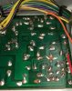
01.06 -4 AmpBoard CU.jpg
 
...C807 in my receiver (1972-8-21) it has the .04uF Ceramic Cap.
The service manuals I have call out a 3.3uF 50V Electrolytic cap.
Better in that location with an electrolytic? or small film cap?

The 0.04uF ceramic capacitor is C808 (not shown in the 2230 schematic or parts list, but seen on the board illustration). The nearby C807 is the 3.3uF 50V electrolytic capacitor.

QUESTION:
Here are two caps (with triangle on it) .1uF 200 WV
are these Matsushita the caps to keep in the receiver
that sound good?...C760 0.1uF 200V cap listed...

C760 is part of the output zobel (with R777), no need to replace.

On the P750 boards, the 100pF ceramic capacitor at C761 (installed on the solder side) is in the signal path and should be upgraded to a C0G type.

Low pass filter.jpg
 
Update:

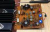
Finished P800--Regulated Power Supply Assy, here is the before pic unfortunately with the pulled up traces:

01.07 -1 Regulator Board Traces.jpg


Here is the board reinstalled with repairs. I have a roll of copper tape that i was going to
use but it is placed somewhere safe in an undermentioned location. Here is the business
side of the board:

01.07 -2 Regulator board Installed..jpg


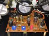
Here is the component side of the same P800 board. You'll notice film caps, where ceramics were
as I have inventory of these caps so there is no shipping charge.
Morgan Jones. (1999). Valve Amplifiers, Newnes, 2nd ed. discusses
not using any ceramic caps in audio amplifiers, period.

"Ceramic capacitors This have no place in analogue audio circuitry!"
He continues, "Ceramic capacitor excel as high frequency bypasses
in digital circuitry where there poor stability of value and low 'd' is not a problem."

That is good enough for me.
Here is the half-way point for one P750 Power Amplifier Assy
Ceramics to be replaced before re-installation.
NOTE: Hi end Wiha screwdriver after Scheiss Kopf Hund found it
in the garage, then chewed the rotating end and swallowed it.


01.07 -4 PowerAmpAssy.jpg


Oh Boy I get a break again, as I misplaced my amp and heat sink assy
and I'm not going to start on the other one until I find this one. Put is somewhere
safe, then life happens, kid, dogs, wife, etc, stop and place parts in safe place,
then more life and now I'm stuck for a bit.

It always get tougher if you try to clean up between...then even more
stuff is unseen. I like the Jim Williams/Bob Pease approach to bench
management. Then you clean, oops.

Keep the trash bucket away from the bench, I've found more good stuff
that I didn't know fell in there that years ago I always go through my trash
before I empty it. Kind of like an investigator looking for tidbits of information, but
I look for way word tools trying to leave the bench or parts that don't want to be
installed. Now its SUB ASSEMBLIES hiding in plain sight.

-- Spike
 

Attachments

  • 01.07 -3 RegulatorBoard Component Side.jpg
    01.07 -3 RegulatorBoard Component Side.jpg
    125.5 KB · Views: 5
Last edited:
I found the amp board and heat sink assy. As I installed a new light fixture on the bench
so I could see and improved the out ventilation flow of solder fumes from the bench as well,
I've been getting I'll from the fumes again, and no matter what I did, the fumes went
to the face....So, hopefully that is taken care of now, along with 2nd covid vaccine which
put me down for about a week. The first one was without issue, even the arm wasn't sore. :)

Now I'm looking at two things to finish up the boards,
and stressing to upgrade everything for my little girls birth day in 13 days.

I've wanted to upgrade some of the 50 year old Transistors...
looking for parts and data sheet, they all end up with some spam
from a China company displaying the incorrect parts.

I was hoping to upgrade the transistors on the amp board and other boards
with newer high purity, low noise devices. And I guess
I could put the incorrect pin out on some and twist the leads,
but was hoping I got the correct ECB parts--NOT.

QUESTION:

To keep the heat temp blob on the board? Or is that a replacement item?
on the trace side of the board is a thermistor to cut off incase of over heating the heat sink.
What about the individual thermistor? On that one I have two extra resistors.

I missed this and then read the service bulletin.

Any advise appreciated.

-- Spike
 
Everybody is different when it comes to transistors. I am a minimalist. I don't replace them unless they are known bad or known troublemakers. Units with diff pairs always get a new set. But replacing them probably isn't the worst thing. I did have trouble setting bias on a 2230 after replacing H751 - 2SC945 with a KSC945. Never figured out what the problem was but when I put the old transistor back, the bias set properly. I leave thermistors alone also unless they are burned or something.
 
Update:

Almost finished up both amp boards. Have to go back to the first and replace some additional resistors that went out of spec
in the second amp board. Want to keep the receiver symmetrical. Also trying to get rid of as many carbon comps as possible
and replace with modern carbon films. I also found that the original green film/carbon/solid resistors depending on who was building
the boards and what was in stock...start to fall apart, at least the outsides...then that has me thinking about the insides of them,
it's like their heat damaged. But the inside if helical cut or spiral cut grooves in the substrate, perhaps the resistors are
still okay.

From Section 13.
1. voltage adjustment was still spot on at 35.58V at R810 on the regulator board.

2 Idle current adjustment, Got worrired after i removed the DBT and started to meausure at full power.
Nothing I did for the newly finished amp board made any different with it bias setting. Either pot,
so I did a quick look didn't notice anything, but still heat and turning them didn't make a difference,
still about 7mV bias...but the heat was really starting up. so I turned off the receiver.

2a. Low and behold of course the bias reading wouldn't change. I took the clip off the meter lead
and clipped it to the ground side for the bias and left the other side of the lead attached to ground.
But the meter was not attached to the ground left of the emitter resistors. That was an easy fix,
so I just clipped everything up proper from J757 & J759 and dialed in 5mV.

Question:
Shouldn't this be 10mV if we are measuring through both emitter resistors?

Checked the line, it was 116 VAC.
Then checked left and right channel B+ at the ampboards:
They matched with 66.6 Vdc with 6.6VAC then down to 23mVAC of ripple
on each channel. So from 66.6 Vdc with 23mVAC that is about .035%
which isn't bad.

I have more boards and more parts to go.

Here is the 2nd amp board:

01.07 -6 2ndAmpBoard.jpg


Here is the 1st amp board:

01.07 -7 1st AmpBoard.jpg


I cleaned those small heat sinks too, you wouldn't know it by looking at them.
More work on these boards too.

The good news is no DBT issues. Bias is holding, so I'll just let the amp burn in and check it in the afternoon.

-- Spike

Question:
On the other boards with the 1n60 germanium diodes, when they are white inside,
are they fried? See in the first pic in the back ground.
 
Hi Spike, I'm just now reading about your restoration. Good work. It's going to be a great gift for your girl! Also thank you for serving our country. Keep going, Brother!
 
Since the service manual has you set bias to 5mV across one emitter resistor, I’m pretty sure it needs to be set to 10mV if you measure across both emitter resistors.
Also, you can test that germanium diode with your DMM Diode Test function looking for about a 0.3V voltage drop.
 
Last edited:
Hi Small Fuses, thank you and yes I'm keeping it going, thanks for encouragement.

Hi Steven, Yes, that is what I surmized, figured I'd check with what the Marantz-perts do and know.
Good info on the germanian diode, to check when I get to that board.

QUESTIONS:

Cap questions, no questions regarding the gray caps.
I haven't taken out the boards yet with the following caps:
White 'Lytic capacitors -
Purple 'Lytic capacitors -

-- Spike
 
The 0.04uF ceramic capacitor is C808 (not shown in the 2230 schematic or parts list, but seen on the board illustration). The nearby C807 is the 3.3uF 50V electrolytic capacitor.

C760 is part of the output zobel (with R777), no need to replace.

On the P750 boards, the 100pF ceramic capacitor at C761 (installed on the solder side) is in the signal path and should be upgraded to a C0G type.

View attachment 2196702


Then, from Ben,
I have another pic but my question is this,
There was one 100pF cap on the board,
and after seeing your post, I put another
100pF soldered to traces as your pic shows.

Reading some other posts, is it correct to add
the other cap to the trace side of the board with
the board also having a 100pF cap on top of the board?

01.07 --8 100pf Caps.jpg

I ask because I don't know,
and as we come to realize we keep asking questions
so that we have the correct parts in place.

The process is iterative (meaning going going back and forth or
revisiting what's been done and reviewing to ensure the board
meets the minimal specification (which we are improving upon).

Of course sometimes that depends on who you are asking.
Everyone's ears, systems, experiences, skills and knowledge
are different...some like beer, some like ale, some like it hot
some like it cold. If it is for you, then do it up what you think best.

It is what it is.

Those large tan mylar caps (and ceramics) on these boards, while I've not listened to it in
this receiver yet, they test extremely good. D is 0.000 across the spectrum from 100Hz to
100kHz. Maybe at 100kHz they might have D of 0.001 or 0.002. The potted polystyrene
caps had a D of 0.005 at 100kHz. There IS something sweet about polystyrenes.
Heck I have some giant Teflons that won't fit in the receiver.

There are big differences between solid state stuff and tube stuff. Tube stuff has
higher voltage 500V - 600V and physically larger parts than smaller solid state.
In short, you need twice the inventory and not much besides .6W and up rated resistors
are interchangable.

Those polystyrene's are calling out and want to be used! I here ya guys, I here ya.

-- Spike
 
Last edited:
Next up, the phono board ready for install:

You'll notice parts changed, transistors, pots, out of spec resistors one side was high,
so both got replaced. The board was cleaned a few more times.
I was really considering Polystryenes or Micas for the ceramics.

I was toying with the idea of replacing the two input coupling caps with some potted
polystryenes that would be good here. But then I'd have to mount them off board
and upside down. Hmmm Still thinking.

Component Side:
01.07 -8 ComponentSide.jpg


Then here is the business end of the board, the trace side. You'll see my board will have two sets
of scratches sometimes. Around the edge of the component lead when my desolder iron slips when
trying to get the lead up from the board sometimes.

The other you might note some of the green might scratch off when I'm using a pic
or a scraper to ensure there is no solder bridge across/between traces.

This board used the almost too thick .050 Kester 44 63/37 base with 2% silver added to
the mix for Sn62, Pb36, Ag02. The .050 solder has plenty of rosin flux in it and it just takes
a second to flow and wet. The thinner solders no to much flux and you have to sit there and
really push the solder, the flux is very small in the.031 diameter.

Trace Side:

01.07 -8 TraceSide.jpg


The trace side of board in post #52 above cleaned up as well as this one. I think I cleaned this one two more times after the pic.
 
Back
Top Bottom