• Please note that Audiokarma will be offline briefly for updates early on Monday morning, September 28th.

Marantz 2230 Gift, for whom?

Then, from Ben,
I have another pic but my question is this,
There was one 100pF cap on the board,
and after seeing your post, I put another
100pF soldered to traces as your pic shows.

Reading some other posts, is it correct to add
the other cap to the trace side of the board with
the board also having a 100pF cap on top of the board?

View attachment 2226715

...

The 100pF on the solder side of the board is the input low-pass filter capacitor, C761. In your P750 boards, is the component side 100pF capacitor connected to R751 and ground?
 
The 100pF on the solder side of the board is the input low-pass filter capacitor, C761.
Yes and it is there.

In your P750 boards, is the component side 100pF capacitor connected to R751 and ground?
Yes, that is how I connected it. As shown in your pic. It's on the other side of R751 (1K) to ground.


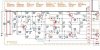
In the following pic to the left, the red box shows the C7XX 100pF cap added to the other side of the R751 to ground.

P750 Assy Schem with-100pF cap.JPG
 
Ben, that is the one I placed there per your post #50 in this thread. I think some of your
earlier build pics showed them with Ceramic Disc on the component sid,
and since you're one of the big dogs here on AK :bowdown: I just figured you placed
the G0G on the solder side of the board and connected it to the 1K resistor
and ground. Since I didn't want to place a onesey parts order for C0Gs,
it would make them something like $6.50 parts each. :deal:

Or, parallel two 47pF caps there PITA--simpler to use the silver micas I had;
EVEN at the expense of +20PPM of TempCo, :dunno:
typically as follows:
C0G = 30 PPM
Mica = 50 PPM

Yes, C7XX capacitor was placed in the schematic by me to show it properly.:bigok:
My hand drawn stuff isn't so good. It's quicker and simpler to modify a graphic
that exists, then to create the circuit from scratch or make parts in Multisim.

No worries, better to be safe than sorry. If the amp portion starts acting funny

I'll know where to look -- LeeStereo. :whip:

In the mean time :beerchug: might be in order.

I appreciate you assistance. :music:
 
Still in research and parts acquisition.

The question of vellum vs milky white Mylar.
I've got to go back to the vellum thread and read up on it again. LINK
I didn't take notes. Or put them somewhere and I'm not sure where.
Choices are as follows around post #101:
White translucent 48lb Vellum card stock - favorable reviews, 10 sheets $4.95
25 sheets of 0.005 "dura lar" film. $18
1 sheet Hobby Lobby - $.50 Passed by today but forgot to check it out. vellum or Mylar.
Double Sided Adhesive Tape Kaisiking 5mm / 10mm x 25M Heat Resistant High Adhesion Transparent Acrylic Tape $9.99

So I'll put the resources here to remember them.

In spite of buying the cap kit from patfont, I had to order caps
because I didin't know and assumed it came with all the caps
for the 2230 receiver. NOT.

Not happy and pat offered to take the kit back.
Time is valuable, especially on a first one of these.


*******My "drop in kits" do not supply AM/FM boards and never did.
Your the first who was not pleased. As stated I would have been glad to do a return and full refund.


Still it was 39 capacitors short that I was expecting though.
Not happy to have to spend more time ordering caps,
Checking lead spacing etc. So for just about every I trying to
narrow it down to 5mm lead spacing for the following:
P150 AM Tuner Board
P300 MPX Decoder Board
P500 FM detector Board
P550 Muting Board

Lots of UKLs that MBura had listed.
I assume the low leakage are beneficial in these
boards for better function.

The one thing I did though was pay a little extra
for the 105*C UKLs. If I recall they have better
rubber seals, maybe a bit more electrolyte
and more secure leads, as said by a famed
engineer and capacitor designer. Any way,
they should last longer then the 2000 hour 85*C
when used in the same location.

Some other slight changes I wanted were also
different then the standard wima metalized line.

Where they were available,
I used the small Nichicon
Mylar and Aluminum foil caps.
No wiggeling inside the cap
as there is with metalized foils.
My description of the phenomena
for Everyman.

Kemet PolyPropStacked Caps.
Check against some old inventory of
Panasonic ECQs that aren't made any longer.

We are living in a great time for doing this
sort of thing with all the information and good
parts available...while they last. End of life
parts is now more of a reality than we realize.
More and more manufacturing is going cheap
break it and throw it away.

Shut eye time again.

Almost, I assume the back side of the face plate is black type silicone
that holds in the dial neutral density filter and the black o rings around
the push buttons. I was thinking of the fast dry Right Stuff silicone.
But this feels more like a stiffer black caulk.

*******My "drop in kits" do not supply AM/FM boards and never did.
Your the first who was not pleased. As stated I would have been glad to do a return and full refund.
 
The 2220B "power supply" board survived well.

I use a Hakko 936 soldering station and Cardas solder, easy on easy off.


Taking my next break, then set to the clean the amp board P800 or 850.
Oh and that lovey Effing cap and Marantz would have failed their IPC test.

Part of what we learn is how to make electronic assemblies that last AND are
serviceable. AND bending over the snap mount terminals...I'm preaching
to the choir. I'll have to scrape the trace, solder a wire running from the
trace to the new snap in terminal and back.

It's too ugly to take pics. At least I can take some of repairing this abomination!
I started out so happy so early in the morning too.

Hey patfont, how the heck did your test amp survive all those cap changes?
Did you cheat and make some boards up in China so that changing caps
would be a snap?

Stay tuned for tomorrow's hunt for the 3/8 inch scraper thing or, how else
can Spike ruin his little girls receiver before she even gets it. NAAAHHHH.
Have the fun is figgering out how to fix it.

Good night boy's and girls.
 
*******My "drop in kits" do not supply AM/FM boards and never did.
Your the first who was not pleased. As stated I would have been glad to do a return and full refund.
Hi Pat, and as I explained in post #25 on Mar 19, 2021 that I didn't not know your kit didn't include those additional caps.
I also explained that you offered to give me a full refund If I sent all the caps back. Due to time, and that I had installed some
caps already, I Mentioned I'd keep them.

Now, if I was unscrupulous, I would have taken down all the part numbers and ordered the parts direct, but I didn't.
Somewhere, I mentioned that I had some concerns about some of the cap types, however i trust your ears and
read through many of your cap try out threads etc. And also concluded these are good parts and Nichicon is an excellent
brand cap along with Elna Silmic II, and even the budget Dayton film & foil cap (which physicist colleague of mine loves.
The only real issue is not the quality, but the perceived not pricey enough for audiophile use. So while not a "name brand"
it won't increase my "social status" using the cap. Too bad, I'm going to use it any way. They are good caps also, so again,
thank you pat.

So, I'm puzzled, why the late reply? That post is two months old?
 
The 2220B "power supply" board survived well.
I use a Hakko 936 soldering station and Cardas solder, easy on easy off.
Yes, I'm also sure you didn't bend the snap in leads down onto the trace?
Keeping the snap in leads vertical soldering to a nice sized trace with glue
on the opposite side would have held it in place just fine for marantz.

However, maybe the parts would move around too much when they wave
or immersion soldered the boards during manufacturing? This and other
issues are why the IPC came about, to develop manufacturing standards
in the late 1950s. This has some interesting information about the IPC: LINK

I'm sure the Cardas solder is fine, however it has a wide elastic temp,
of 20 degrees (364-384º F) increases the possibility of a bad joint if something
moves or vibrates etc. The nice thing about the 63/37 or 62/26/2 (2-silver)
is there is only one temperature going from liquid to a solid.

I tried to find the Cardas Wetting temp, and a lesser known temp where
the solder joint locks in. The latter was described to me by the good folks
who make the electric jets our services use; i.e., F-16, F-22, F35.
Generally they described three temperatures for 63/37 solder:
1. Melting Temp
2. Wetting Temp
3. Locking Temp

I posted this comparison for Everyman, if interested:

Solder 3 types Melt Range.JPG


Sorry that I couldn't keep the links active in the citations. It is what it is.

Another issue for me personally, once you learn the correct way to do things
it's difficult to either unlearn them or not do them.

I hope that clarifies my thinking.
 
I am really not on here that much anymore and just happened to see it, no biggie.
Good luck with the rebuild! Pat

Hi Pat, No worries. Thank you for explaining. You did right with me so I have no issues.
Now that I've gotten settled in a bit and more familiar with the Marantz's etc,
I do see that from many to most of the kits don't have the caps for the other boards.

I was trying to get this done quickly--well it isn't happening that way.
I did send my little girl a letter (through the U.S. Mail [which has not arrived yet])
with a Happy Birthday and a chit that is good for one Marantz 2230 when Dad
finishes working/upgrading/replacing parts on it. That is what is on Dads bench!

She always loves to run to the mail box to see if we got anything, so it will
be a joyous occasion when she gets a letter from the postman (includes both sexes,
or do we just say gender non specific?). Postperson just doesn't have the
correct ring to it. And it's not in the spell checker either. Siri doesn't know it,
at first it thought it was Model Policy for Police Pursuits, etc. After several
retries it came up with BS then "Mail Carrier" as a "gender-neutral" term.
However I think of that like a "Golf Carrier" the wheeled thing we attach
our gold club bag to.

You catch my drift man.

Don't mind me, I get slap happy sometimes. It's hard to tell in text
when someone is being sarcastic. For those of you who are old
enough to remember Rowan and Martin's Laugh-In, I'm not funny,
as I'm like the straight man, Dan Rowan...
... and beautiful downtown Burbank.
 
And yes I did bend the leads for a good mechanical connection, and then solder.
Pat, you did that with the snap in caps? I'm impressed. So how many times did you desolder, desolder, unbend, remove, replace with next test cap
until you were finished with your capacitor shoot out? Did the boards live to tell about it? You did, of course, but the boards how did they hold up?

Now that I think about it, now that I know what did, I'm sure I wouldn't have
the same problem that I had initially. Knowledge and skill are a good thing.
 
The 2220B power supply board is robust, and survived well.
The snap in Nichicon KG and KS were tested in a 2230, the leads do not need to be bent.
 
It's ok to be electronically challenged...you just don't want to remain there.

Here is a review for Everyman. Of course, I need the review also,
lest I forget; and at my mature age, forgetting isn't quite the norm--YET.

If you already know this, no worries, some of us might find it helpful.

In general, the incoming signal is on the base, and exits via the emitter.
Vcc comes through the collector, but if it has a resistor in series with the collector,
depending on which side of the resistor feeds back to the base,
you have either:
Collector feedback bias
Emitter feedback bias
Maybe I can draw a pic...better to find a site and link.

This isn't very simple but you get the idea: LINK

This is so I remember, where I'll find it.

I'll find a textbook instead and I'll find a pic and upload it.
Here is a pic of them from Floyd's electronic devices text (p255):

View attachment 2245649


View attachment 2245641


View attachment 2245642


View attachment 2245644


View attachment 2245645


View attachment 2245646


Floyd, T,L. (2012.) electronic devices: electron flow version, 9th ed. Pearson
Education, Inc., publishing as Prentice, Hall, Upper Saddle River, New Jersey. U.S.A.
 
Back
Top Bottom