• The move to the new server is done. There are some software and database maintenance updates in process. This has us passing the hat around to help out. We appreciate any donations. Seriously, even a dollar helps. The payment page may be found here - https://www.audiokarma.org/support.html

Marantz 2275 rebuild

bitomaxsp

Member
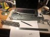
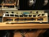
I am rebuilding my 2275. It was in a bit of tired shape i'd say. But when i disassembled it it was more that tired. I guess everyone is aware what is on the picture. I am make 3D model now to 3D print this lamp holder. Once i'll validate that model is ok in reality i'll make it public so everyone could print it. Mine is just melted over time and then it was cracked after bad LED conversion done by prev owner.
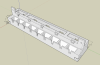
Screen Shot 2021-10-02 at 17.03.58.png

Also i am expecting quite a big order from mouser that should cover almost everything in the amp. More update will follow.
 
Register to hide this ad
I also have a 2275 in need of a refurbish, but I want to say...

Wow, you live on a volcano? IN the middle of nowhere?
Do you guys grow your own food?
How long does it take for Mouser parts delivery?
 
Wouldn't lay too much blame for the lamp housing damage on the previous owner. The housing was a bad choice of materials to hold lamps that get hot. Just replaced one on a 2250 that imploded in place.
 
Wouldn't lay too much blame for the lamp housing damage on the previous owner. The housing was a bad choice of materials to hold lamps that get hot. Just replaced one on a 2250 that imploded in place.
I agree about the material, but housing is just physically broken in several places.
At least i wouldn't tight metal to plastic like crazy :)
 
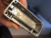
Here's the one I took outta the 2250. You don't have to tighten the screws much for the brittle plastic to crack. Often it's cracked with the original lamps in it, and the screws probably are in the same place the factory put them. The cracks and missing corner in the photo were there when I took the cover off.
2250Housing.JPG
 
Here's the one I took outta the 2250. You don't have to tighten the screws much for the brittle plastic to crack. Often it's cracked with the original lamps in it, and the screws probably are in the same place the factory put them. The cracks and missing corner in the photo were there when I took the cover off.
View attachment 2359150

Holy Christ! Mine is way way better. Why am I not satisfied?!. :) Anyway, i hope my model will help to maintain our AMP in good shape. Guy i am ordering 3D prints from broke his printer, so i have to wait.
 
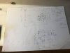
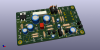
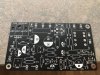
While i was soldering back and forth components on P800 I noticed that traces are going to fall off the board. So here is my initiative project: P800 rebuild in Kicad. I'll make it BLACK :) Should be very in line with overall Marantz design.
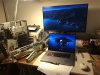
Did some measurements already:
IMG_3289.jpg
 
This is final and i am going to send it to production in a few days. Do not pay attention to wrong 3d models. They placed correctly but missing some pins :) Color will be black of course.

P800.png P800-back.png
 
Last edited:
Awesome work. Was there a reason why you made a 3-layer board vs 1-layer? Did you print the lamp housing yet?

There no 3 layer boards. I made 2. Bottom is the ground, top - power.
Housing is printed, but i didn't get it yet. I'll post an update here once i get it;

Reason i rerout the P800 is that after soldering traces unglued. And I want black PCB - just esthetics (or my crazy with).
 
While i am waiting for P800 PCB to arrive i am doing other PCBs :)
Since my amp (i think as many others) is only partially LED converted I decided to make proper LED conversion for indicators. This PCB is supposed to be direct replacement for original one.
There is a choice to have LED converted dial pointer (or leave it as lamp, less components to mount then).
This PCB is a bit longer (on the side) than original one. Following design is final. It would be green. Probably i'll have several not in use :)

Front (towards dials):
upload_2021-10-18_16-36-37.png

Back (towards trans):
upload_2021-10-18_16-37-34.png
 
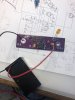
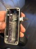
Along with P800 i also ordered a PCB for a device that allows to find band-end of the file capacitor (provided one has oscilloscope). I built it yesterday and use to find band end on those caps i ordered for P700 and PE01.
Here is how it works. Its build process and how it look inside. I am not the author. I just repeat what Mr.Carlson did in his video. It work awesome i must say.
 

Attachments

  • IMG_3381.jpg
    IMG_3381.jpg
    91 KB · Views: 82
  • IMG_3382.jpg
    IMG_3382.jpg
    81 KB · Views: 83
  • IMG_3383.jpg
    IMG_3383.jpg
    81 KB · Views: 84
Back
Top Bottom