• The move to the new server is done. There are some software and database maintenance updates in process. This has us passing the hat around to help out. We appreciate any donations. Seriously, even a dollar helps. The payment page may be found here - https://www.audiokarma.org/support.html

Marantz 2275 rebuild

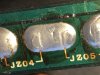
Touch the cap and wait until device switches LED. When lowest amplitude is found that side is band end then just mark it.

Right LED (large amplitude)
IMG_3386.jpg

Left LED (lower amplitude) Band ed is on the left side.
IMG_3387.jpg

That i repeated for all films.
MKS (polyester) are not sensitive at all, i think it's du to production technology.

These are big 1uF MKP
IMG_3388.jpeg
IMG_3389.jpeg

And these are MKS series:
IMG_3390.jpeg
IMG_3391.jpeg
IMG_3393.jpeg

Band end usually goes to the lowest impedance part on schematic.
 
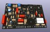
Now some words about P800 replica (not exact though) :)

First of all i checked it actually matches all other parts. It was a concern for me.
IMG_3398.jpeg
IMG_3399.jpeg
IMG_3400.jpeg
IMG_3400.jpeg

As you can see match is perfect! I am super satisfied. And color matches Marantz style (+3dB to music power) :)

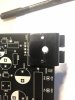
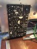
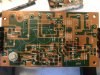
This is the original board. As you can see, 13V line takes it's voltage from Collector of H804. And there is a pad on the bottom that connects through the bolt to the tab of the transistor.
I didn't know how to make a footprint in KiCad like that — main reason i did it otherwise.

R815. In my design this resistor intentionally made larger (i mean footprint, same as R801 by the way) than others as it dissipates quite a lot of heat, hence brownish board.
That resistor must be installed on the long leads to allow better heat dissipation. (i'll show it later).
IMG_3402.jpeg

This is quite it. Stay tuned and alive.
 

Attachments

  • IMG_3401.jpeg
    IMG_3401.jpeg
    137.8 KB · Views: 103
  • IMG_3397.jpeg
    IMG_3397.jpeg
    84.1 KB · Views: 102
Last edited:
Time for an update!

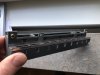
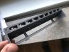
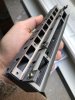
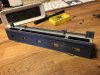
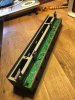
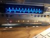
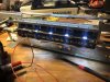
I finally had time to assemble LEDS completely! My STL model was printed and removed unnecessary parts, drilled additional holes (4 in total). I decided that it is easier to drill them, than print and i was right.
It fits absolutely perfect. Looks great. Attached is the ZIP with STL file that you can all use.
 

Attachments

  • IMG_3425.jpg
    IMG_3425.jpg
    73.7 KB · Views: 89
  • IMG_3426.jpg
    IMG_3426.jpg
    82.6 KB · Views: 89
  • IMG_3427.jpg
    IMG_3427.jpg
    96.3 KB · Views: 90
  • IMG_3509.jpg
    IMG_3509.jpg
    115 KB · Views: 89
  • IMG_3510.jpg
    IMG_3510.jpg
    126.4 KB · Views: 88
  • marantz2275#2stl.zip
    marantz2275#2stl.zip
    21.1 KB · Views: 32
While i am waiting for P800 PCB to arrive i am doing other PCBs :)
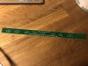
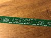
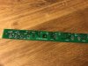
Since my amp (i think as many others) is only partially LED converted I decided to make proper LED conversion for indicators. This PCB is supposed to be direct replacement for original one.
There is a choice to have LED converted dial pointer (or leave it as lamp, less components to mount then).
This PCB is a bit longer (on the side) than original one. Following design is final. It would be green. Probably i'll have several not in use :)

Front (towards dials):
View attachment 2370525

Back (towards trans):
View attachment 2370527

Regarding this proper LED conversion kit!
It looks good. Thought i figured that i did couple small mistakes.
1. I should have took SMD LEDS (but i ordered TH even before i decided to make this board). SMD will give better esthetic result since lighting will be more even.
2. Rect copper under the bolt heads should be round and bit bigger. This is fixed in Rev.B

I have 4 boards left of these.
 

Attachments

  • IMG_3505.jpg
    IMG_3505.jpg
    130.1 KB · Views: 64
  • IMG_3506.jpg
    IMG_3506.jpg
    134.4 KB · Views: 59
  • IMG_3507.jpg
    IMG_3507.jpg
    137.3 KB · Views: 64
  • IMG_3512.jpg
    IMG_3512.jpg
    105.1 KB · Views: 66
  • IMG_3513.jpg
    IMG_3513.jpg
    123 KB · Views: 67
Nice work! May I make some suggestions? First you may want to spray paint the inside surfaces of your beautiful new lamp housing flat white to reflect light better. Secondly, and if you do redesign the function lamp board you may want to add a filter cap after each diode pack to reduce light flickering. Likely it would fit on the back of the board and be a tantalum type to fit. I use 68uF on my custom SMD warm white LED fuse lamps to do that along with a small bridge rectifier and it works great.
 
Time for an update!

I finally had time to assemble LEDS completely! My STL model was printed and removed unnecessary parts, drilled additional holes (4 in total). I decided that it is easier to drill them, than print and i was right.
It fits absolutely perfect. Looks great. Attached is the ZIP with STL file that you can all use.

Where did you get the new lamp housing?
 
Nice work! May I make some suggestions? First you may want to spray paint the inside surfaces of your beautiful new lamp housing flat white to reflect light better. Secondly, and if you do redesign the function lamp board you may want to add a filter cap after each diode pack to reduce light flickering. Likely it would fit on the back of the board and be a tantalum type to fit. I use 68uF on my custom SMD warm white LED fuse lamps to do that along with a small bridge rectifier and it works great.

i made tests on the bench before ordering the board. 100Hz flickering is not noticeable with LEDs. That is why i didn't add it.

Good point about paint. Unfortunately i had no choice about plastic, hence it's gray
 
Thanks for the quick reply! I'm confused. You've posted pictures of new, black P700 boards. So you have had these manufactured, yes? I'm just curious on the ball park cost. I need a few for different models, not the 2275.
 
Back
Top Bottom